
Influence on Recorded Tape
Our next concern then was to assess the effect of stray fields on tape moving on a tape recorder or tape winder, and especially, to find a maximum permissible value of field strength below which no deterioration occurs.
What we were looking for in our tests were partial erasure or loss in playback level, increase in distortion, increase in noise and, ultimately, recording of the stray field onto the tape.
Depending on its source, a stray magnetic field can take many forms from a very homogenous one (from a distant source) to a rather sharply focused one (from a source near or in the tape machine). As the latter case was thought to be most detrimental and as we deliberately wanted to establish the worst case conditions, we decided on a test setup where the stray field in the tape path was generated by an iron-core inductor with a large air gap of some 7 mm. Also, again looking for the worst case, we found that stray fields perpendicular to the tape surface had the largest effect.
Our tests were carried out using a Nagra 4.2 L tape machine and Agfa PE-46 tape, since it was our aim to test a tape right in the middle of the coercitivity range to obtain typical results which would also be of significance for other tapes. Pure sinewave signals of different frequencies and magnetization levels were recorded and the tape subjected to a calibrated stray field during playback. Playback level and waveform were monitored by an RMS voltmeter (weighted or unweighted), an oscilloscope and a distortion analyzer.
It soon became clear, however, that it was not possible to obtain conclusive results with that method. After getting some very puzzling test results we decided to analyze the playback waveform on a spectrum analyzer and there we found the reasons for the misleading test results using conventional equipment. Also, the spectral analysis proved extremely instructive, and in some cases surprising.
It would exceed the scope of this report to give details on all the many tests we made. They can be summarized as follows:
- DC stray field: increase in low-frequency noise starting at 50 Oe, loss in playback level starting at 100 Oe, no appreciable increase in distortion up to 200 Oe;
- 50 Hz AC stray field: partial erasure of original signal, and recording of 50 Hz stray field starting at 10-50 Oe.
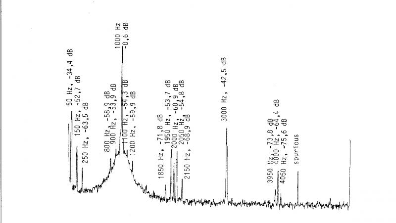
It is interesting to note that the stray field is recorded not only in the form of the 50 Hz fundamental and its harmonics but also in the form of sidebands around the original recorded signal and its harmonics. The number and amplitude of these sidebands increase with increasing stray field strength and their effect is clearly audible even for stray fields as low as 20 Oe.
Much to our surprise, we also found that small stray fields between 10 and 50 Oe add 50 Hz sidebands to the even-numbered harmonics of the original signal only (Fig. l. a - d). The mechanism causing this peculiarity is not yet fully understood and there is some evidence that it may in part be due to the form of the magnetic field used in the test setup. Further work will be necessary to find a satisfactory explanation. It should be noted that all tests were made using 50 Hz power line frequency fields as these are most commonly encountered in practice (60 Hz in the USA will give similar results). Stray magnetic fields of higher frequency are most unlikely in a studio.
Figure 1 Spectrograms of pre-recorded tape subjected to AC stray field during playback
Parameters:
Recorded test fequency 1 kHz with harmonics
Record level 0 dB
Tape machine Nagra 4.2L
Tape Agfa PE46
Stray field 50 Hz AC, sinusoidal
Figure 1a: Stray Field 0 Oe
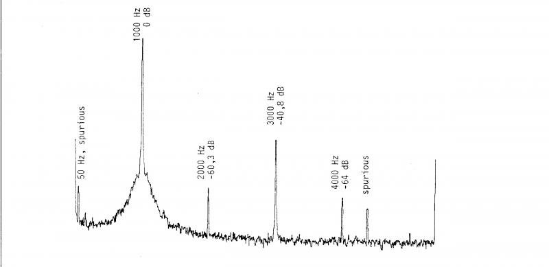
Figure 1b: Stray Field 10 Oe
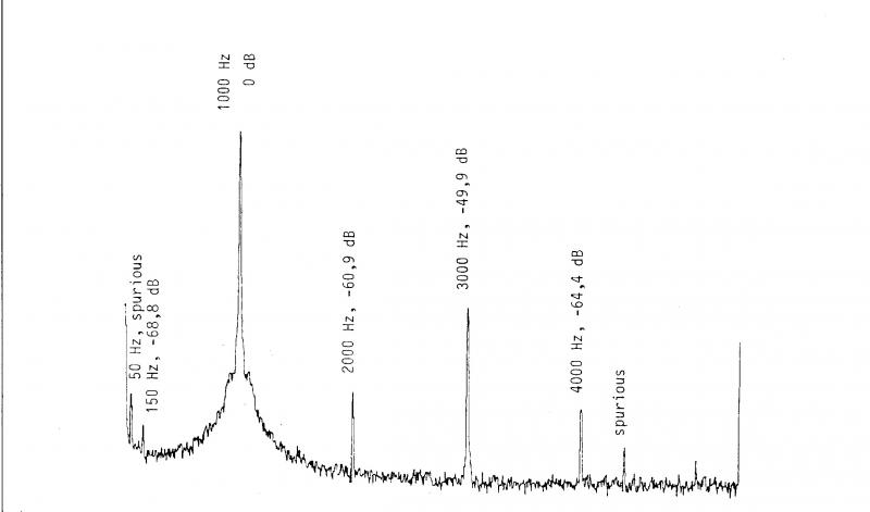
Figure 1c: Stray Field 20 Oe
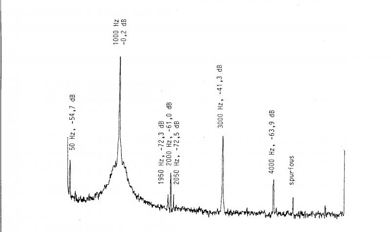
Figure 1d: Stray Field 50 Oe

")