Measurements of stray magnetic fields in sound archives
IASA Technical Committee
Report on Measurements of stray magnetic fields in sound archives
Erhard Aschinger, Phonogrammarchiv der Osterreichischen Akademie der Wissenschaften
First published in the Phonographic Bulletin No. 27 - July 1980
Table of contents
Introduction
One of the big advantages of magnetic tape over any other recording medium is that the stored information can be erased and the tape used over and over again. If, however, tape is to be used as a permanent store of information, as in a Sound Archive, this property is a very big disadvantage indeed. It would be fine if one could - by some still unknown process similar to that of fixing a photographic picture - freeze the once recorded sound for good.
Aside from complete erasure, which can be considered the extreme case, the magnetic inscription on the tape can be influenced by a number of factors including:
- Humidity
- Fungus
- Chemicals
- Age
- Print-through
In addition, and perhaps most dangerously, the magnetic inscription can be influenced by external magnetic fields.
G.A. Knight and others have thoroughly investigated the influence of AC and DC magnetic fields on stored tape. In particular, they studied print-through, partial erasure, increase in distortion and noise, etc., caused by external fields originating from electric machines, lightning strikes and the like.
In his paper G.A. Knight suggests that a value of 25 Oe (not distinguishing between AC and DC) may be accepted as a level “below which very little degradation is likely to occur”. No information is given, however, on the degree of degradation that is considered to be acceptable. Also, there appears to be no literature on what happens to tape being moved through a stray magnetic field.
At the Phonogrammarchiv, we came across this question when we discovered that many technical devices used in a studio exhibit quite strong stray magnetic fields - in fact, even tape recorders of prominent manufacture show field strengths which, at first, shocked us and then prompted a closer study. The question is, what happens to a pre-recorded tape travelling through a magnetic field, AC or DC, of, say, 5 Oe, or 50 Oe, or more.
Assessment of Stray Magnetic Fields
To get an idea on what is involved, we started by assessing the stray magnetic fields of objects and equipment typically used in a Sound Studio or Archive. The measured values are tabulated in the Appendix. All test objects were tested for AC and DC fields. Where there is no entry for one of these it was non-existent, or negligible, that is, below 0.5 Oe.
In all DC measurements, the magnetic field of the earth was not compensated for (this would have complicated the measurements unnecessarily), so there is an uncertainty of ± 0.4 Oe which we found acceptable for our purpose.
From the table it can be seen that all pieces of equipment incorporating permanent magnets exhi-bit strong DC stray fields, i.e., loudspeakers (especially small ones), dynamic microphones, dynamic headphones (Beyer DT 48), moving-coil instruments, etc. AC stray fields originate of course from power transformers in mains-operated equipment (including tape recorders).
|
Stray Magnetic Field Test Results |
|||
|---|---|---|---|
|
Test Objects:
Measure values: Test Equipment: Bell Inc. Model 640 Incremental Gaussmeter |
|||
| Test Object | Measurement Location | H (Oe) | D (mm) |
| Loudspeakers | |||
| TANNOY Arden | front | 19.0 | 150 |
| back | 17.0 | 130 | |
| side | 3.0 | ||
| top | 5.0 | ||
| TANNOY Berkeley | front | 20.0 | 150 |
| back | 36.0 | 150 | |
| side | 4.0 | ||
| top | 1.0 | ||
| ACRON 100c | front | 150.0 | 120 |
| back | 60.0 | 120 | |
| side | 50.0 | 100 | |
| top | 160.0 | 80 | |
| B & O Type M | front | 30.0 | 20 |
| back | 1.0 | ||
| side | 1.0 | ||
| top | 1.0 | ||
| Microphones | |||
| AKG D19 | front | 90.0 | 30 |
| side | 30.0 | 12 | |
| AKG D900 | side | 30.0 | 2 |
| AKG D190 | front | 90.0 | 30 |
| side | 30.0 | 12 | |
| AKG D58 | front | 90.0 | 30 |
| side | 30.0 | 12 | |
| AKG D160 | front | 90.0 | 30 |
| side | 30.0 | 12 | |
| AKG D24 | front | 90.0 | 30 |
| side | 30.0 | 12 | |
| Headphones | |||
| KOSS Pro-5 LG | inside | 100.0 | 50 |
| outside | 20.0 | 20 | |
| KOSS ESP-9 (electrostatic) | power supply | 10.0 AC | |
| AKG K240 | inside | 100.0 | 25 |
| outside | 20.0 | 5 | |
| AKG K140 | inside | 45.0 | 20 |
| outside | 25.0 | 10 | |
| BEYER DT48 | inside | 230.0 | 70 |
| outside | 150.0 | 70 | |
| side | 80.0 | 50 | |
|
Tape recorders |
|||
| STUDER B67 | maximum AC | 0.5 AC | |
| loudspeaker top surface | 30.0 DC | ||
| in tape path | 7.0 DC | ||
| pinch roller sol.* top surface | 15.0 DC | ||
| in tape path | 7.0 DC | ||
| STUDER B62 | pinch roller sol.* top surface | 10.0 DC | |
| in tape path | 6.0 DC | ||
| STUDER A67 | pinch roller sol.* top surface | 11.0 DC | |
| in tape path | 5.0 DC | ||
| VU-meters | 20.0 | 6 | |
| REVOX A77 | pinch roller sol.* top surface | 20.0 DC | |
| in tape path | 10.0 DC | ||
| NAGRA 4.2 | loudspeaker top surface | 8.0 | |
| in tape path | 5.0 | ||
| side | 15.0 | 20 | |
| Stellavox SP7 | loudspeaker top surface | 8.0 | |
| in tape path | 5.0 | ||
| power supply | 1.0 AC | ||
| Tandberg Type 11 | loudspeaker top surface | 20.0 | 20 |
| in tape path | 5.0 | ||
| Uher 40001C | loudspeaker front | 20.0 | 30 |
| in tape path | 12.0 | ||
|
Miscellaneous Equipment |
|||
| LEEVERS-RICH Bulk Eraser | in tape path (10.5" reel) | 600 to 800 AC | 150 |
| bottom | 10.0 AC | 100 | |
| sides | 10.0 AC | 100 | |
| Hand-held De-Magnetizer Type 1 | tip | 800.0 AC | |
| shaft | 400.0 AC | ||
| handle | 500.0 AC | ||
| back | 1500.0 AC | 150 | |
| Hand-held De-Magnetizer Type 2 | tip | 600.0 AC | |
| back | 1000.0 AC | 120 | |
| Welding Transformer 1.8 kVA Model PROMETHEUS | idling | 40.0 AC | 100 |
| short circuit | 400.0 AC | 500 | |
| Desk-Top Telephone | back of receiver | 22.0 DC | 30 |
| left side of case | 4.0 DC | ||
| PPM Instruments Ernest Turner | front | 100.0 DC | 50 |
| Mixing Console (FELS) | 0.8 AC | ||
| Mixing Console (Custom) | 0.5 AC | ||
| Tone Generator (Heathkit) | 3.0 AC | ||
| Tone Generator (Custom) | 0.2 AC | ||
| Universal AF Filter | 5.0 AC | ||
| Pro-Amplifier (QUAD) | 0.6 AC | ||
| Pro-Amplifier (Kenwood) | 0.5 AC | ||
| Pro-Amplifier (Custom) | 0.5 AC | ||
| Multimeter UNIGOR 6e | top | 70.0 DC | 60 |
| side | 15.0 DC | 50 | |
| bottom | 10.0 DC | 10 | |
| 60 W Fluoresent Lamp | near internal choke | 2.0 AC | |
| Typewriter IBM | 0.8 AC | ||
| Typewriter OLIVETTI Editor 3 | top | 1.5 AC | |
| bottom | 3.0 DC | ||
*sol.= solenoid
Influence on Recorded Tape
Our next concern then was to assess the effect of stray fields on tape moving on a tape recorder or tape winder, and especially, to find a maximum permissible value of field strength below which no deterioration occurs.
What we were looking for in our tests were partial erasure or loss in playback level, increase in distortion, increase in noise and, ultimately, recording of the stray field onto the tape.
Depending on its source, a stray magnetic field can take many forms from a very homogenous one (from a distant source) to a rather sharply focused one (from a source near or in the tape machine). As the latter case was thought to be most detrimental and as we deliberately wanted to establish the worst case conditions, we decided on a test setup where the stray field in the tape path was generated by an iron-core inductor with a large air gap of some 7 mm. Also, again looking for the worst case, we found that stray fields perpendicular to the tape surface had the largest effect.
Our tests were carried out using a Nagra 4.2 L tape machine and Agfa PE-46 tape, since it was our aim to test a tape right in the middle of the coercitivity range to obtain typical results which would also be of significance for other tapes. Pure sinewave signals of different frequencies and magnetization levels were recorded and the tape subjected to a calibrated stray field during playback. Playback level and waveform were monitored by an RMS voltmeter (weighted or unweighted), an oscilloscope and a distortion analyzer.
It soon became clear, however, that it was not possible to obtain conclusive results with that method. After getting some very puzzling test results we decided to analyze the playback waveform on a spectrum analyzer and there we found the reasons for the misleading test results using conventional equipment. Also, the spectral analysis proved extremely instructive, and in some cases surprising.
It would exceed the scope of this report to give details on all the many tests we made. They can be summarized as follows:
- DC stray field: increase in low-frequency noise starting at 50 Oe, loss in playback level starting at 100 Oe, no appreciable increase in distortion up to 200 Oe;
- 50 Hz AC stray field: partial erasure of original signal, and recording of 50 Hz stray field starting at 10-50 Oe.
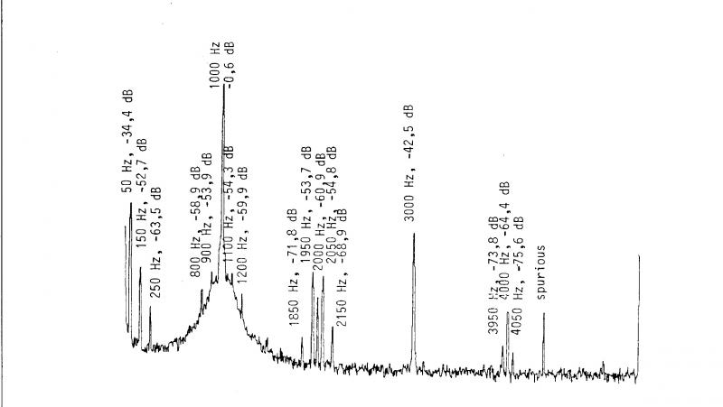
It is interesting to note that the stray field is recorded not only in the form of the 50 Hz fundamental and its harmonics but also in the form of sidebands around the original recorded signal and its harmonics. The number and amplitude of these sidebands increase with increasing stray field strength and their effect is clearly audible even for stray fields as low as 20 Oe.
Much to our surprise, we also found that small stray fields between 10 and 50 Oe add 50 Hz sidebands to the even-numbered harmonics of the original signal only (Fig. l. a - d). The mechanism causing this peculiarity is not yet fully understood and there is some evidence that it may in part be due to the form of the magnetic field used in the test setup. Further work will be necessary to find a satisfactory explanation. It should be noted that all tests were made using 50 Hz power line frequency fields as these are most commonly encountered in practice (60 Hz in the USA will give similar results). Stray magnetic fields of higher frequency are most unlikely in a studio.
Figure 1 Spectrograms of pre-recorded tape subjected to AC stray field during playback
Parameters:
Recorded test fequency 1 kHz with harmonics
Record level 0 dB
Tape machine Nagra 4.2L
Tape Agfa PE46
Stray field 50 Hz AC, sinusoidal
Figure 1a: Stray Field 0 Oe
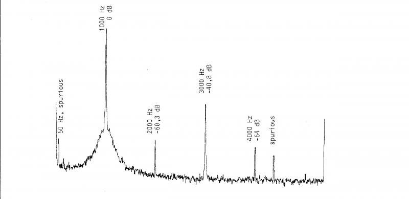
Figure 1b: Stray Field 10 Oe
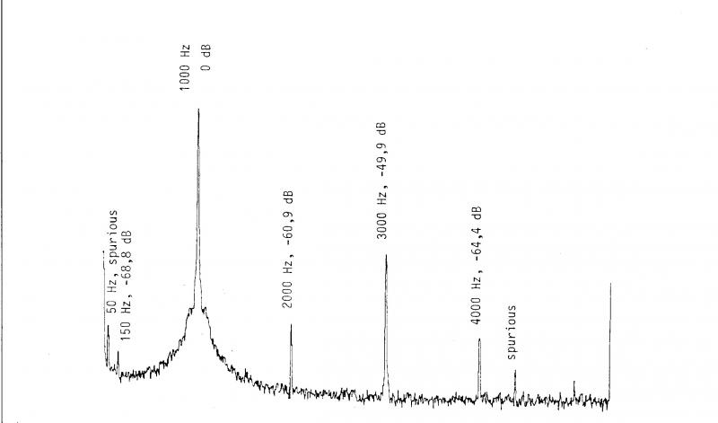
Figure 1c: Stray Field 20 Oe
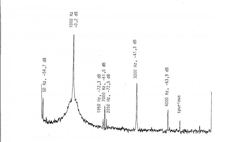
Figure 1d: Stray Field 50 Oe
Warning Label
As our study has shown that already rather weak stray fields can harm archival tapes and that these values are within the range exhibited by equipment used in a studio, it would seem wise to have some safeguard against any “magnetic accidents”.
We propose, therefore, to establish a new warning label to be attached to any piece of equipment liable to emit stray magnetic fields, similar to the well-known radioactivity warning label. It should show a universally understood symbol for a magnet and should indicate the nature of the field, AC or DC, and give the worst-case 5 Oe-distance or enveloping radius in mm.
Conclusions
It has been shown that stray magnetic fields as low as 10 Oe AC or 50 Oe DC can cause permanent damage to recorded magnetic tape. Including a safety factor of 2, it is recommended to keep tapes away from fields exceeding 5 Oe AC or 25 Oe DC.
In practice, special care must be taken with carrying cases housing tape recorder, recorded tapes, dynamic microphones and dynamic headphones adjacent to each other. On the other hand, loudspeakers (except those in miniature enclosures) are not nearly as dangerous as has been thought up to now. Also, the AC and DC stray fields found in the tape path of tape recorders can be considered harmless. They could, however, easily be avoided completely by proper design of the machine.
This paper was presented at the IASA Technical Committee Session in Salzburg and some very interesting suggestions were made in the discussion period. These focused on magnetic hazards to tape during transport. These problems will be dealt with in a subsequent report which we hope will also include data on metal detectors, magnetic gates (in airports, etc.), electric trolleys, fork lift trucks, electric railways, air freight, etc.
Acknowledgements
Dipl.Ing. Franz Lechleitner (Phonogrammarchiv der Österreichischen Akademie der Wissenschaften) for invaluable help with measurements;
Dr. Werner A. Deutsch (Kommission für Schallforschung der Osterr. Akademie der Wissenschaften) for doing the spectral analyses;
Institute für Allgemeine Elektrotechnik der Technischen Universität Wien, for assistance in instrumentation.
Bibliography
G.A. Knight: “Factors Relating to Long Term Storage of Magnetic Tape,” Phonographic Bulletin, no. 18, (July 1977), pp. 15-35.