5.4 Reproduction of Analogue Magnetic Tapes
5.4.1 Introduction
5.4.1.1 Analogue magnetic tape recording technology has permeated every area of the recording industry since its mass distribution and popularisation in the post WWII era. Technological advancements made tape the primary recording format for professional recording studios, and manufacturing developments made the reel recorder affordable for the domestic market. The introduction of the Philips Compact Cassette in 1963 put a recording device within the grasp of many people and it became possible and practical for people to record whatever seemed important to them.Virtually every sound archive and library holds analogue magnetic tape recordings, and PRESTO (Wright and Williams 2001) estimates there are over 100 million hours of analogue tape recordings in collections throughout the world, a figure in no way contradicted by the IASA survey of endangered carriers (Boston 2003). Since the 1970s sound archivists recommended quarter inch analogue reel tape as the preferred archival carrier, and in spite of inherent noise and impending chemical decay, some still stand by them today as a stable carrier. Nonetheless, the imminent demise of the analogue tape industry and the consequent and almost total cessation of the production the replay equipment demand that immediate steps be taken to transfer this vast store of recorded cultural history to a more viable system of management.
5.4.1.2 Magnetic tape was first made commercially available in Germany in 1935, but it was the commercialisation of the American market after 1947 that drove its popularity and eventual standardisation. The first tapes were manufactured on a cellulose acetate backing and this continued until the introduction of polyester (polyethylene terephthalate PET, commercially known as Mylar). Tape manufacturers produced both acetate and PET tapes with an acetate binder, which was gradually, and most commonly, replaced from the late 1960s by a polyester urethane binder. BASF manufactured tapes on PVC from the mid 1940s until 1972, though it gradually introduced its own range of polyester from the late 1950s onward. Though PVC was primarily the province of the German manufacturer BASF, 3M also produced a PVC tape from around 1960; Scotch 311. Rarer are paper backed magnetic tapes, which date from the late 1940s to the early 1950s. Cassette tapes have always been manufactured on polyester. In 1939 the magnetic pigment used was γFe2O3, often called the oxide, and although subsequent improvements in particulate size, shape and doping increased performance and reduced noise, this formulation has remained virtually the same for almost all analogue reels and type I cassettes. Type II cassettes are CrO2 or cobalt doped Fe3O4, III (rarely encountered) are dual layered with both γFe2O3 and CrO2 and IV are metal (pure iron).
5.4.1.3 The materials that bind the magnetic particles to the tape substrate, called binders, are often identified as that part of the tape most susceptible to chemical breakdown. This is especially so with polyester urethane binder tapes which most commonly use a PET substrate from the 1970s, though AGFA and BASF and their subsequent owners, Emtec, used a PVC based binder on many of their studio and broadcast tapes, notably 468.
5.4.2 Selection of Best Copy
5.4.2.1 Recordable media such as magnetic tape tend not to have multiple copies of the same generation. With the exception of cassette, audio on tape was only infrequently mass replicated and so the sound archivist must choose between generational duplicates. As a rule, the most original copy is the best copy to select for the purposes of preservation. However, the original tape may have suffered some form of physical or chemical degradation, such as hydrolysis, whereby a duplicate made in accordance with proper procedure prior to that decay might be better. Tape rarely shows visible signs of decay or damage so, where multiple copies of an item exist, the best approach is to carefully spool through, and then audition the tape to determine the best copy.
5.4.2.2 Curatorial decisions must also be made to ensure that the most appropriate or complete duplicate is selected. This is primarily an issue where the tapes have been produced as a result of a sequential production process such as audio mastering or in the production of sound for film or video.
5.4.3 Cleaning and Carrier Restoration
5.4.3.1 Tape Cleaning: Dirty or contaminated tapes should be cleaned of dust and debris with a soft brush and low vacuum before spooling. Deformed reels may seriously damage tapes, especially in the fast winding mode, and must be replaced before any further steps are carried out. The tape should be carefully spooled guiding the tape so as not to cause damage. The tape may then, if necessary, be spooled on a tape-cleaning machine that has a soft cloth or other lint free material cleaning surface. This may also be beneficial after treatment for hydrolysis (see below). Some tape cleaning or restoration machines pass the tape across a sharp surface or blade, which removed the top layer of oxide. Such machines were developed for the re-use of recorded tapes and are not recommended for archival tapes. Special attention should be paid to dirty cassette tapes as some reputable double capstan machines may damage dirty tapes during replay.Without adequate tape tension control a loop may develop between the capstans.
5.4.3.2 Leader Tapes and Tape Splices: Many tapes have splices either through editing or the addition leader tapes. Such splices are likely to have failed, either through dry failure of the adhesive, or bleeding of the adhesive layer. The former must be replaced. Bleeding splices constitute a more serious problem. The adhesive may spread from the splice to the adjacent layers which may have encouraged the dissolution of the binder. It may also cause the layers to adhere to each other and increase speed fluctuations. Old adhesive must be removed using a solvent that does not damage the binder. Highly purified light fuel is an appropriate solvent and may be applied using a Q-tip or lint free cloth. It is advisable to keep the amount applied to the tape to the minimum required, and no more than would be applied with a Q-tip. As with all solvents, a small amount should be tested on an unused portion of the tape. The tape should be left unwound for a few minutes to ensure full evaporation. Evaporation may be accelerated by an air stream. It is sometimes necessary to replace or add leader tape to enable the complete recording on the tape to be played.
5.4.3.3 Hydrolysis (Sticky Shed Syndrome): When replayed, many of the tapes manufactured since the 1970s show the artefacts of a chemical breakdown of the binder. Often described as sticky shed syndrome, the main component of the reaction is hydrolysis1 , by which term it is often described. It is typified by a sticky brown or milky deposit on tape heads and fixed guides, often accompanied by an audible squeal and reduction in audio quality.
5.4.3.4 The following treatments represent various approaches to the treatment of binder degradation:
5.4.3.4.1 Room Temperature, Low Humidity: Hydrolysis involves the splitting of a chemical bond through the introduction of water, and providing that an irreversible recombination has not subsequently occurred, hydrolytic reactions should be reversible through the simple process of removing all water. This can be achieved by placing the tapes in a chamber approaching 0% relative humidity (RH) for extended periods of time, up to several weeks. Slightly elevating the temperature increases the reaction time. Tests have shown that this treatment, while successful in some cases does not always completely reverse all the artefacts of a degraded tape (Bradley 1995).
5.4.3.4.2 Heated Respooling: Sometimes very degraded tapes may bind one layer upon another and uncontrolled spooling may cause damage. In such cases, if baking is not being undertaken, it may be possible to apply warm dry air directly to the point in the tape pack where the tape is sticking, and then commence to unspool the tape at a controlled rate of 10-50 mm per minute.
5.4.3.4.3 Elevated Temperature, Low Humidity: An approach commonly used in the treatment of hydrolysed tapes is heating the tape in a chamber at a stable temperature approaching 50 ºC and 0% RH for period of around 8- 12 hours. The temperature of 50 ºC probably equals or exceeds the glass transition temperature2 of the tape binder, however, whether that has a long term effect on the physical characteristics of the tape when returned to room temperature is unclear. It does, however, have a positive short term electro-acoustic effect by returning the replay characteristics to original condition. Interleaving with new tape may be of benefit in reducing the level of print activity, which can be activated by temperature increases. Tapes should be rewound a number of times to reduce the effects of print through caused by elevated temperatures (see 5.4.13.3).
5.4.3.4.4 This latter procedure has a high success rate, but should not be carried out in a domestic oven. Domestic ovens have poor temperature control, which may exceed safe thresholds. Additionally the thermostat control of such ovens cycles back and forward across of range of temperatures and this action may damage the tape. A microwave oven should never be used as it heats small parts of the tape to very high temperature and may damage the tape and its magnetic characteristics. A laboratory oven is preferred, or other stable low temperature device. Higher temperatures should never be allowed as these may cause deformation of the tape.
5.4.3.5 Exposing tapes to controlled, elevated temperatures as described above should be undertaken very carefully and only where absolutely necessary.
5.4.3.6 Restoration may be only temporary, yet should enable replay for transfer. Anecdotal evidence is that hydrolysed tapes which require longer treatment are becoming more prevalent.
1. Hydrolysis: A chemical decomposition by addition of water, or a chemical reaction in which water reacts with a compound to produce other compounds
2. Glass Transition Temperature;That temperature at which an adhesive loses its flexibility and becomes hard, inflexible, and “glasslike.”
5.4.4 Replay equipment: Professional Reel Machines
5.4.4.1 As analogue reel tape has been the mainstay of the sound recording and archiving community for decades the virtual cessation of the manufacture of reel player/recorders is a major crisis in the sound archiving community. Very few new professional tape machines are currently available from manufacturers, possibly only from Otari who continue to make a single machine, which may be described as the third generation of their mid-range model when compared to their earlier range, and Nagra Kudelski, who still list two portable field recording analogue tape machines as available. Not all machines meet the necessary replay specification (below) and archives must check for compliance before making a purchase. The alternative is to purchase and restore second hand machines, and the market in high end analogue reel machines is quite strong. It is recommended that only widely used machines should be purchased as this will facilitate the acquisition of parts and maintenance. The characteristics of a suitable archival reel machine include the following:
5.4.4.2 Reel Replay Speeds: The standard tape speeds are as follows: 30 ips (76.2 cm/s), 15ips (38.1 cm/s), 7.5 ips (19.05 cm/s), 3¾ ips (9.525 cm/s), 1 7⁄8 ips (4.76 cm/s) and 15⁄16 ips (2.38 cm/s). The need to replay all these speeds will depend on the makeup of the individual collections. No single machine will play all 6 speeds, but it is possible to cover all speeds with two machines.
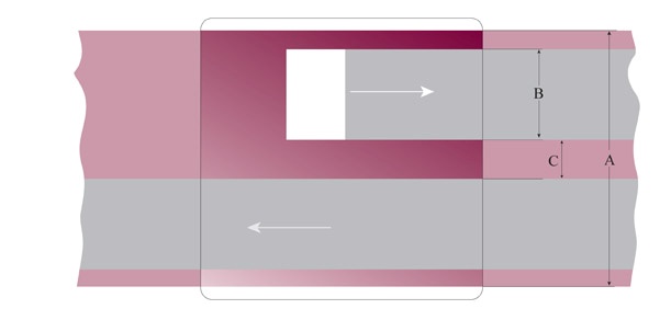
5.4.4.3 Mono and stereo 1/4 inch recording equipment come in 3 basic track configurations; full track, 1/2 track and 1/4 track. There are variations in the actual track width according to the particular standard. A tape replayed with a head with less replay width than the actual recorded track width will exhibit an altered low frequency response known as the fringe effect, and show poorer signal to noise than optimum. So a recorded track width of 2.775mm replayed with a 2mm stereo head will result in a loss of signal to noise ratio of approximately 2dB. The fringe effect is of the order of about +1dB at 63 Hz at 19.05 cm/s (7.5 ips) (McKnight 2001). A tape replayed with a head with a wider replay width than the actual recorded track width will exhibit slightly worse signal to noise and may pick up unwanted hiss or signal from adjacent tracks.”It amounts to the ratio of 1.9 mm to 2.1 mm, corresponding to a 1 dB level shift for these head widths; or 1.9 mm to 2.8 mm, corresponding to 3.3 dB for these widths.” (McKnight 2001) In practice these compromises are often accepted for small variation in track width in replay provided no unwanted signal is included (note that the unrecorded portion of previously erased tape may exhibit higher noise levels). Though some machines may include half track and 1/4 track replay heads, it may be necessary to have more than one machine to deal with these standards.

| A | B | |
|---|---|---|
|
IEC1 94-1 (pre 1985) |
6.3 mm, (0.248 in) |
6.3 mm, (0.248 in) |
| NAB 1965 |
6.3 mm, (0.248 in) |
6.05 mm (0.238 in) |
|
IEC 94-6 1985 |
6.3 mm (0.248 in) |
5.9 mm (0.232 in) |
Fig 1. section 5.4 full track head configuration and dimensions.

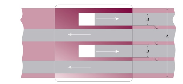
| A |
maximum recording width1 |
B | C | |
|---|---|---|---|---|
| Ampex |
6.3 mm, (0.248 in) |
6.05 mm (0.238 in) |
1.9 mm (0.075 in) |
2.14 mm (0.084 in) |
|
IEC 94-6 1985 2 track |
6.3 mm, (0.248 in) |
5.9 mm (0.232 in) |
1.95 mm (0.077 in) |
2.00 mm (0.079 in) |
| IEC home stereo (pre 1985) |
6.3 mm, (0.248 in) |
6.3 mm, (0.248 in) |
2.0 mm (0.079 in) |
2.25 mm (0.089 in) |
| NAB 1965 |
6.3 mm, (0.248 in) |
6.05 mm (0.238 in) |
2.1 mm (0.082 in) |
1.85 mm (0.073 in) |
|
IEC-1 Time code DIN mono half track |
6.3 mm, (0.248 in) |
6.3 mm, (0.248 in) |
2.3 mm (0.091 in) |
1.65 mm (0.065 in) |
|
IEC 94-6 1985 Stereo |
6.3 mm, (0.248 in) |
5.9 mm (0.232 in) |
2.58 mm (0.102 in) |
0.75 mm (0.03 in) |
|
IEC-1 Stereo (pre 1985) Mono half track |
6.3 mm, (0.248 in) |
6.3 mm, (0.248 in) |
2.775 mm (0.108 in) |
0.75 mm (0.03 in) |
|
IEC ½ inch |
12.6 mm (0.496 in) |
5.0 mm (0.197 in) |
2.5 mm (0.098 in) |
Fig 2. section 5.4 two track and half track head configuration and dimensions.
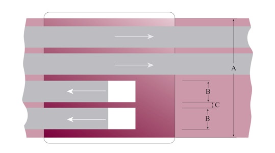
| A | B | C | |
|---|---|---|---|
|
IEC1 NAB |
6.3 mm, (0.248 in) |
1 mm (0.043 in) |
0.75 mm (0.43 in) |
Fig 3 section 5.4 quarter track head configuration and dimensions.
| A | B | C | |
|---|---|---|---|
|
IEC Philips |
3.81 mm, (0.15 in) |
0.6 mm (0.02 in) |
0.3 mm (0.012 in) |
Fig 4 Section 5.4 Stereo Cassette head configuration and dimensions.
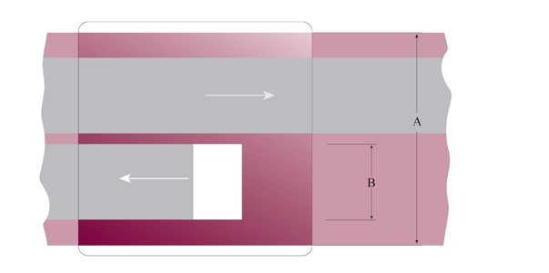
| A | B | |
|---|---|---|
|
ANSI Philips |
3.81 mm, (0.15 in) |
1.5 mm (0.06 in) |
Fig 5 Section 5.4 Mono Cassette head configuration and dimensions.
5.4.4.4 Head dimensions are specified in different ways in the European and US standards. Initially, the International Electrotechnical Commission (IEC), predominately referred to by European manufacturers, specified the tape with regard to the centre of the tape and the distance between the tracks, while the American based standards referred to the size of the recording track width defined diagrammatically with respect to one side. The size of the tape itself, has changed over time, initially a quarter of an inch, it was defined as 0.246 ± 0.002 inch (6.25 ± 0.05 mm) and later as 0.248 ± 0.002 in (6.3 ± 0.05 mm)”. IEC defines recording width in a full track recording in the following manner,”A single track shall extend over the whole width of the tape.” (IEC 94 1968:11), whereas the American based standards define the size of the recorded track to slightly less than the width of a 0.246 inch tape at 0.238 +0.010 -0.004 inch track size (this is a pragmatic solution to the problem of “grooves” in head wear and extends to all track dimensions). IEC later changed their full track width to 5.9 mm (0.232 inches). The number of standard track widths specified in figs.1 to 5 suggests that there is very little standardisation. (Eargle 1995, Benson 1988, IEC 94-1 1968, 1981, IEC 94-6 1985, NAB 1965 McKnight 2001, Hess 2001).
5.4.4.5 The net effect of replaying tapes on mismatched head widths is discussed in 5.4.2.2 above. It is important to attempt to assess the correct head width with which the original tapes were recorded and to then replay them on the most appropriate machine available. half” and 1” two track recordings are generally made in half track configuration only, and with specialised professional recording equipment with the intention of providing very high quality analogue audio. The same type and standard of equipment is required for replay, and an even closer attention to the detail of the record/replay standards.
5.4.4.6 Multitrack recordings range from domestic 1/4” standards to professional 2” and care must be taken to ensure the replay of those tapes is accurate. If time code has been recorded as part of the recording it must be captured and encoded in such a way that it may be used for later synchronisation (see 2.8 for file formats).
5.4.4.7 Tape machines should be capable of replaying signals with a frequency response of 30 Hz to 10 kHz ±1 dB, and 10 kHz to 20 kHz +1, -2 dB.
5.4.4.8 The equalisation on a reel replay machine should be capable of being aligned for replaying NAB or IEC equalisation, preferably being able to switch between them without re-alignment.
5.4.4.9 Wow and flutter unweighted better than 0.05% at 15 ips, 0.08% at 7.5 ips, and average variation from true speed better than 0.1%.
5.4.4.10 A professional archival reel machine should also have gentle tape handling characteristics so that it does not damage the tape during replay. Many of the early and middle generation studio machines depended on the robust characteristics of the modern tape carrier for their successful operation. These machines may cause damage to older tapes, or to long play tapes or thin tapes used for field recording.
1. Maximum recording width refers to the width measured from the outside edge of the outer tracks (see section 5.4.4.4)
5.4.5 Replay equipment: Professional Cassette Machines
5.4.5.1 Professional cassette replay machines are unavailable new. Also, the second hand market for professional cassette machines is not as strong as that for reel machines making it difficult to locate appropriate equipment. This represents a critical problem for sound archives, many of whose collections hold large numbers of recorded cassette tapes. Thus it should be a matter of priority for any collection with cassette tapes to seek out and acquire professional cassette replay machines. The characteristics that distinguish a professional machine from a domestic machine, apart from the replay specification, include solid mechanical construction, the ability to adjust replay characteristics and head azimuth, and the provision of balanced audio outputs. Many high quality audiophile machines provide some of the above characteristics. The characteristics of a suitable archival cassette replay machine include the following:
5.4.5.2 Replay speeds 17/8 ips (4.76 cm/s) (note that speeds of 15/16 ips and 3 ? ips may also be required for replay of specially recorded cassettes).
5.4.5.3 Variation from speed better than 0.3%.Wow and flutter weighted better than 0.1%.
5.4.5.4 Replay frequency response of 30 Hz to 20 kHz +2, -3 dB.
5.4.5.5 Ability to replay Type I, II, and IV cassettes (as required).
5.4.5.6 Most cassette machines will automatically select the correct replay equalisation by reading the holes or notches on the top of the cassette housing or shell to determine the tape type. A few machines do not read the notches but have a switch that the operator uses to select the appropriate equalisation. Type III cassettes may be problematic as they are enclosed in shells identical to Type I cassettes, while requiring the same replay equalisation curve as Type II cassettes.Where no explicit option to replay Type III has been provided by the playback machine, it may be necessary to use a deck with adjustable equalisation or to rehouse the tape in a Type II shell (see Section 5.4.12.5 Cassette Enclosures).
5.4.6 Maintenance
5.4.6.1 All equipment will require regular maintenance to keep it in working order. However, as analogue replay equipment is going out of production, it is necessary to make plans for spare parts as manufacturers will only maintain spare parts for a finite, and possibly short, period of time.
5.4.7 Alignment (equalisation below)
5.4.7.1 Analogue equipment requires regular alignment to ensure that it continues to operate within specification. It is recommended that heads and tape path be thoroughly cleaned every 4 hours of operation, or more frequently if required, using a suitable cleaning fluid such as isopropyl alcohol on all metal parts. Rubber pinch rollers should be cleaned with dry cotton buds or with cotton buds dampened with water as necessary. The older, original rubber pinch rollers can gradually become brittle if cleaned with alcohol, increasing wow and flutter. The new generation of polyurethane pinch rollers, generally coloured dark green, may dissolve if cleaned with alcohol. Heads and tape path to be demagnetised every 8 hours of operation, tape path and replay characteristics checked for alignment every 30 hours of use and equipment should receive a total alignment and check every 6 months.
5.4.7.2 In the same way that machines and tape are going out of production, suitable test tapes are likewise becoming difficult to obtain, and some are now unobtainable. It behoves the archivist to acquire enough open reel and cassette test tapes to manage the transfer of their collection.
5.4.8 Speed
5.4.8.1 Although speed correction is also possible in the digital domain, it is better to avoid such later digital correction and to carefully choose replay speed in the first transfer process, and to document chosen speed and justification. Tape recorders are very likely to have exhibited inaccurate speed characteristics due to fault, poor alignment, or in some cases, unstable power supply. Consequently no tape speed should be taken for granted.
5.4.9 Capstan-less Machines and Non-linear Speeds
5.4.9.1 Some early generation reel recording machines were designed to run without the control of the capstan and pinch roller, and consequently exhibit steadily increasing speed. If these tapes are played at a standard, unchanging speed, the resultant signal would decrease in pitch as the tape was replayed. To play the tape correctly the replay speed must change in the same manner as the recording speed. Some of the more recent replay machines, such as those made by Nagra or Lyrec, have incorporated a voltage driven external speed control which allows the operator to design a simple circuit with a curve that matches the speed of the original. Some of the last generation replay machines, such as the Studer A800 series, incorporated microprocessor control allowing for programmable manipulation of the speed, and others like the Lyrec Frida allowed the speed to be manipulated in the MIDI environment. However, care should be taken in assuming that the speed increase is linear. The early capstan-less machines were made cheaply and the speed varied according to the load on the reel, the speed increase is often less at the beginning or end of the tape where one or the other of the reels is full making a graph of the replay speed over time far from linear.
5.4.10 Replay Equalisation
5.4.10.1 The signal representation in most analogue audio formats is deliberately not linear in terms of frequency response. Correct replay, therefore, requires appropriate equalisation of the frequency response.
5.4.10.2 The most common of the equalisation standards for audio replay of analogue tape are as set out below (Table 1 Section 5.4). It should be noted that equalisations have developed over time. The current standards are given in bold type, together with their date of introduction. Earlier recordings must be replayed by applying the respective historical standards and simple additional circuits may be utilised. The overlapping of old and new standards should be taken into account when decisions are to be made for tapes recorded in times of transition. Prior to that there were a number of manufacturers’ standards.
| 30 ips, 76 cm/s |
IEC2 AES |
(1981) current standard | ∞ | 17.5 μs |
| 30 ips, 76 cm/s |
CCIR IEC1 DIN |
(1953–1966) (1968) (1962) |
∞ | 35 μs |
| 15 ips. 38 cm/s |
IEC1 CCIR DIN BS |
(1968) current standard (1953) (1962) |
∞ | 35 μs |
| 15 ips. 38 cm/s |
NAB EIA |
(1953) current standard 1963 |
3180 μs | 50 μs |
| 7½ ips, 19 cm/s |
IEC1 DIN(studio) CCIR |
(1968) current standard 1965 1966 |
∞ | 70 μs |
| 7½ ips, 19 cm/s |
IEC 2 NAB DIN(home) EIA RIAA |
(1965) current Standard (1966) (1963) (1968) |
3180 μs | 50 μs |
| 7½ ips, 19 cm/s |
Ampex (home) EIA (proposed) |
(1967) | ∞ | 50 μs |
| 7½ ips, 19 cm/s |
CCIR IEC DIN BS |
(up to 1966) (up to 1968) (up to 1965) |
∞ | 100 μs |
| 3¾ ips 9.5 cm/s |
IEC2 NAB RIAA |
(1968) current standard (1965) (1968) |
3180 μs | 90 μs |
| 3¾ ips 9.5 cm/s | DIN | (1962) | 3180 μs | 120 μs |
| 3¾ ips 9.5 cm/s | DIN | (1955–1961) | ∞ | 200 μs |
| 3¾ ips 9.5 cm/s |
Ampex (home) EIA (proposed) |
(1967) | ∞ | 100 μs |
| 3¾ ips 9.5 cm/s | IEC | (1962–1968) | 3180 μs | 140 μs |
| 3¾ ips 9.5 cm/s | Ampex | (1953–1958) | 3180 μs | 200 μs |
| 17/8 ips 4.75 cm/s |
IEC DIN |
(1971) current standard (1971) |
3180 μs | 120 μs |
| 17/8 ips 4.75 cm/s |
IEC DIN RIAA |
(1968–1971) (1966–1971) (1968) |
1590 μs | 120 μs |
|
17/8 ips 4.75 cm/s cassette |
IEC Type I | 1974 current standard | 3180 μs | 120 μs |
|
17/8 ips 4.75 cm/s cassette |
DIN Type I | (1968–1974) | 1590 μs | 120 μs |
|
17/8 ips 4.75 cm/s cassette |
Type II and IV | (1970) Current standard | 3180 μs | 70 μs |
| 15/16 ips 2.38 cm/s | undefined |
Table 1 Section 5.4 Common Equalisation Standards for Audio Replay of Analogue Tape4
5.4.10.3 At 15 ips and 7.5 ips there is a choice in replay equalisation for reel tapes even for tapes which were recently recorded according to the current standards. However, these are the two most common recording speeds, and care must be taken when choosing a replay equalisation to ensure that it corresponds with the record equalisation. Apart from the standards mentioned in table 1 section 5.4 there are a small number of more current standards intended to achieve better performance but which are different from the commonly accepted standards. At 15 ips Nagra tape recorders have the option to use a special equalisation called NagraMaster. The US version of NagraMaster had time constants ∞ and 13.5 µs, the European version of NagraMaster had time constants 8 and 13µs. Ampex used “Ampex Master Equalization” (AME), also at 15 ips but officially only on particular 1/2 inch mastering recorders introduced in 1958 and sold for several years following (MRL 2001). Logging machines and some popular semi-professional portable equipment were able to record at the very slow speed of 15⁄16 ips (2.38 cm/s). However, it appears that there is no agreed exchange standard for these tapes and any equalisation would have adhered to proprietary conventions.
5.4.10.4 Sometimes any lack of documentation may require the operator to make replay equalisation decisions aurally. Cassette replay equalisation corresponds to the tape type, and care must be taken to ensure that the correct replay equalisation is used. Many tape recordings, specifically private recordings and those of cultural or research institutions that lacked technical support, have been made on un-aligned tape recorders. Unless there is objective evidence that would allow alternate settings, with regard to equalisation, tapes must be treated as properly aligned.
4. Note, IEC refers to IEC Pub 60094-1 4th edition, 1981, NAB to the NAB reel to reel standard 1965 (IEC2), or cassette standard 1973, DIN refers to DIN 45 513-3 or 45 513-4 and AES to AES-1971, and BS to the British Standard BS 1568). Thanks to Friedrich Engel, Richard L. Hess and Jay McKnight for generously supplying information on tape equalisation.
5.4.11 Noise Reduction
5.4.11.1 The signal recorded onto a tape may have been encoded in such a way as to mask the inherent noise of the carrier. This is known as noise reduction. If the tape has been encoded while recording, it must be decoded using the same type of decoder appropriately aligned. The most common noise reduction systems include Dolby A, and Dolby SR (professional), Dolby B and Dolby C (domestic), dbx types I (professional) and II (domestic)although rarely used and TelCom.
5.4.11.2 The alignment of the record and replay characteristics of the tape machine are critical to the adequate operation of noise reduction systems and characteristic line up tones are often included on professionally recorded tapes. The output level, as well as the frequency response can alter the response of the decoding system and it is also important to note that noise reduction may be applied to either IEC or NAB equalisation and must be replayed correctly. Dolby B and Dolby C have routinely been included in most professional cassette decks of recent years and generally do not have line up tones and have a less obvious effect on the signal than the professional systems.
5.4.11.3 Though it is possible to transfer the audio from an encoded tape for decoding at a later time, the multiple variables in alignment can compound the errors and make it difficult to decode accurately once the tape has been transferred. Decoding is better undertaken at the time of transfer.
5.4.11.4 Unless documented, it is difficult to assess whether compact cassettes have encoded with a noise reduction system. As with equalisation, the lack of documentation may require the operator to make such decisions aurally. The right replay is generally characterised by an even level of background hiss, while the fluctuation of this level indicates a wrong playback setting. A spectrum analysis tool can be helpful. If it cannot be determined, copies of cassettes should be made flat.
5.4.12 Corrections for Errors Caused by Misaligned Recording Equipment
5.4.12.1 Misalignment of recording equipment leads to recording imperfections, which can take manifold form.While many of them are not, or hardly correctable, some of these faults can objectively be detected and compensated for. It is imperative to take compensation measures in the replay process of the original documents incurred, as no such correction will be possible once the signal has been transferred to another carrier.
5.4.12.2 Azimuth and Tape Path Alignment: Inaccurate alignment of the record head of the original recording machine means that at replay, the signal retrieved will exhibit a reduced high frequency response, and, in the case of two or more track replay, an altered phase relationship between the two channels. Adjustment of the angle of the replay head such that the relationship of the head is in the same plane as the magnetised field on the tape is termed the azimuth adjustment and this simple adjustment can markedly improve the quality and intelligibility of the retrieved signal. There is no difficulty in training staff in this task, and good binaural hearing is all the measuring technology required. An accurate phase meter or oscilloscope will aid in the adjustment of mono and properly recorded tapes, they may, however, be misleading on tapes recorded on cheap, domestic equipment. In such cases aural judgement of the high frequencies should be relied on. Additionally or alternatively, a software programme providing a real time-spectrogram function can be used. Azimuth adjustment should be a routine part of all magnetic tape transfers.
5.4.12.3 Digital systems may correct the phase relationship of the signal (often described as azimuth correction), however such procedures cannot retrieve the high frequency information that is lost. Azimuth adjustments must be made on the original tape before transfer commences.
5.4.12.4 The vertical alignment of the heads on the original recording machine may present an obstacle to the appropriate reproduction of the signal. This is particularly the case with recordings made on amateur or consumer-grade equipment. In order to obtain a visual representation of the alignment of the tracks on the tape of a recording the following procedure should be followed: Recorded portions of tapes should be protected by a very thin transparent sheet of Mylar or similar transparent material. A powder or suspension of ferromagnetic material, particle size less than 3 µm, is sprayed over the transparent sheet. The magnetic properties of the recorded portion of the tape then make the tracks visible. A carefully marked series of measurement lines on the sheet will aid in detecting misalignment. These tape path adjustments are less frequently required than azimuth adjustment, but if they must be undertaken the replay equipment should be recalibrated by a qualified technician. Every care should be taken to ensure no iron particles remain in contact with the tape as these may damage the replay heads.
5.4.12.5 Cassette Enclosures: The enclosures in which low cost cassette tapes are housed may cause the tape to jam or replay with increased wow and flutter. In such cases it is often beneficial to replace the tape in a high quality screwed enclosure being sure to include the rollers, pressure pad and lubricating sheets.
5.4.12.6 Wow, Flutter and Periodic Tape Speed Variations: There is little that can be done to effectively improve periodic variations in the recorded signal. It is therefore imperative that the replay equipment is thoroughly and carefully checked, aligned and maintained to ensure that no speed related artefacts are introduced.With the availability of high resolution A/D converters and components, it seems possible to retrieve the high frequency (HF) bias signal from analogue magnetic tapes during transfer, which may enable the correction of wow and flutter. There are, however, many significant barriers to realising this, including a lack of available hardware to extract signals of such high frequencies and the inherent unreliability of the bias signal itself. As the procedure is generally time-consuming and complex, and substantial improvements concerning this matter are not to be expected, implementation is unlikely, and even then, only feasible for a limited group of tapes produced under specific circumstances.
5.4.13 Removal of Storage Related Signal Artefacts
5.4.13.1 It is preferable in most cases to minimise the storage related signal artefacts before undertaking digitisation. In linear analogue magnetic recording, for example, print-through is a well-known and disturbing phenomenon. The reduction of this unwanted signal can only be undertaken on the original tape.
5.4.13.2 Print-Through: Print-through is the unintentional transfer of magnetic fields from one layer of analogue tape to another layer on the tape reel. It reveals itself as the pre and post echoes to the main signal. The intensity of print through signal is a function of the wavelength, tape coating thickness, but primarily the spread of the coercivity5 of the particles in the magnetic layer. Almost all print through occurs soon after the tape is recorded and wound onto the pack. The increase in print-through after this reduces over time. Further significant increases in print-through occur only as a consequence of changes in temperature. When the tape is stored with the oxide facing in to the hub, the most common standard, the print on the layer outside of the intended signal is stronger then the print signal on the layer towards the hub of the spool. Consequently it has been frequently recommended that tapes be stored “tail out”, in which case the post echoes are louder than the pre echoes and less obvious. German broadcast standards specified that tapes be wound with the oxide out, in which case the reverse applies, and tapes should be stored “head out”.
5.4.13.3 Printed signals are reduced by the act of rewinding the tape prior to playing, by a process termed “magnetostrictive action”. Systematic tests have shown, however, that it is wise to rewind a tape at least three times to sufficiently diminish print through (Ref Schuller 1980). If the printed signal is very high and it does not respond adequately to rewinding, some tape machines allow the application of a low level bias6 signal to the tape during playback. This selectively erases lower coercivity particles and hence reduces print-through, though it may also have an effect of the signal, especially if over-applied, and should only be used as a last resort and then very carefully.
5.4.13.4 Though print-through can be reduced on the original tape the same level of restoration is not achievable afterwards. Once copied to another format the printed signal becomes a permanent part of the wanted signal.
5.4.13.5 Vinegar Syndrome and Brittle Acetate Tape: Acetate tape becomes brittle with age which may make it difficult to play a tape without breaking. The brittleness occurs as a result of a process of chemical degradation which occurs when the molecular bonds of the acetate compound break down to release acetic acid giving off the characteristic smell of vinegar. Broken acetate tape can be spliced without any signal loss or deterioration, because, as a result of its brittleness, no elongation of the tape occurs. Brittle tapes, however, are also subject to a variety of deformations which hinder the necessary tape-to-head contact for optimal signal retrieval. Though a process of re-plastification would be advantageous,such processes do not exist as yet. Archivists are warned against the chemical processes sometimes suggested as these may not only jeopardise the further survival of the tape,but also contaminate replay equipment and, indirectly, other tapes replayed on such machines. Instead, it is recommended that such tapes be replayed using a recent machine that permits to lower tape tension. This will enable an acceptable compromise between care of the fragile tape and the application of enough tape tension to permit the best possible tape-to-head contact.
5.4.13.6 Physical Tape Memory: Poorly stored and spooled polyester and PVC tapes may also suffer from deformation of the tape. The tape will often retain a memory of that deformation and so make poor tape to head contact, which reduces the signal quality. Repeated respooling and resting may reduce some of this effect.
5. Coercivity; A measure of the intensity of the magnetic field needed to reduce the magnetization of a ferromagnetic material to zero after it has reached saturation
6. Bias; A high frequency signal mixed with the audio during recording to help reduce tape based noise. Devised by Weber in 1940
5.4.14 Wire Recordings
5.4.14.1 Though the principles of wire recordings were demonstrated at the very end of the 19th century, and various dictation machine manufacturers produced working models in the 1920s and 1930s (see 5.4.15 below), it was not until around 1947 that the wire recorder was successfully marketed to the general public.
5.4.14.2 The speed of wire recorders was not standard and varied between manufacturers and even, on occasion, from model to model. After 1947, however, manufacturers mostly adhered to a standard speed of 24 ips and a reel size of 2¾ inches. Wire recorders did not have capstans, and so the speed would change as the take up reels became full. The size of the take up spool was integral to the correct replay of the wire, and very often related to a particular machine or manufacturer. The take-up spool is generally a fixed part of the machine. The height of popularity of the wire recorder was in the years from the mid 1940s till the early 1950s, a period which coincided with the development and introduction of the technically superior tape recorder and the wire was soon considered obsolete. Even in its heyday, the wire recorder was primarily used as a domestic recorder, though some were used for commercial purposes.
5.4.14.3 Though the wire fell quickly from favour, wires were available in speciality outlets until the 1960s. Early reel sizes were large in comparison to the 2¾ inch reels which become the most commonly used reel. Some wires, mostly early in the history of the wire recorder, were made from plated or coated carbon steel, and these may now be corroded and difficult to play. Many wires, however, are in excellent condition being made from Stainless Steel with 18% chromium and 8% nickel, and have not corroded.
5.4.14.4 The principle of wire recorders is comparatively simple, so that the construction of a replay machine is possible. However, the complexity associated with successfully spooling and playing the fine wire without tangles or breakages suggest that the best approach to replay is to use an original machine, though it is worth noting that some experts have modified tape machines to replay wires.When using original machines it is recommended that the audio electronics be overhauled to ensure best performance or, preferably, replaced with audio circuitry using modern components (Morton 1998, King: n.d.)
5.4.15 Magnetic office dictation formats
5.4.15.1 In the decades following World War II a wide variety of magnetically recorded office dictation formats appeared. That the needs of the office differ from other audio recording environments is reflected in their design: reduced size and weight, ease of operation and variable speed were prioritised, usually at the expense of audio quality. Magnetic dictation systems may be broadly divided into tape and non-tape-based formats.
5.4.15.2 Tape in this context includes various forms of wire (see 5.4.14 above), reel and cassette. Some formats may be playable using standard equipment (non-standard cassette formats may sometimes be rehoused and replayed in standard cassette shells for instance) while others may only be played on dedicated format-specific players. Where a choice is available, a decision needs to be made between the two approaches. One entails the use of high- specification, relatively easy to maintain standard equipment, potentially coupled with poor compatibility in tape width, head configuration, replay speed, equalisation, noise reduction etc. The other offers higher compatibility between carrier and player, but very likely at the cost of the lower specification and esoteric maintenance needs of the original format-specific equipment. Tape-based formats can be subdivided into linear and non¡linear speed. The former will present fewer problems if replayed on conventional equipment; the latter may also be playable in this way, but will require speed adjustment (see 5.4.9).
5.4.15.3 Non-tape formats include a bewildering array of discs, belts, rolls and sheets, all featuring magnetically coated surfaces, recorded onto and replayed using heads similar in principle to conventional tape heads. Given sufficient expertise, time and money therefore, it may be possible to build replay devices for some of these formats, incorporating components from more common tape replay equipment. In many cases however locating an original replay machine might be more feasible, and it may be possible to contract a specialist equipped to carry out the work.
5.4.16 Time Factor
5.4.16.1 The time needed for copying contents of audio material varies greatly, and is highly dependent on the nature and status of the original carrier. The step of actually playing the carrier is only one part of the process, which includes respooling, assessment, adjustment and documentation. Even a well documented, good quality analogue tape of 1 hour’s duration will take, on average, twice the time of the length of its recording to properly transfer to a digital carrier. In the mid-1990s the Archivarbeitsgruppe of ARD (Arbeitsgemeinschaft der Rundfunkanstalten Deutschlands) would regard this as optimistic as they postulated a transfer factor of 3 (1 operator: 3 hours of work for 1 hour of material) for the transfer of typical archival holdings of their radio stations. Tapes that exhibit any faults, which require repair or restoration, or need documentation or the assessment and addition of metadata, will take much longer to conserve, transfer and preserve.
5.4.17 Signal Auto detection, auto upload (failings and benefits)
5.4.17.1 It is recommended that all tapes be actively listened to while preservation transfers are being undertaken. However, in response to the sheer quantity of the material to be transferred and preserved, manufacturers of digital archiving systems have been developing ways of automatically monitoring and detecting signal faults allowing for the possibility of unattended transfers. The savings in time are obvious, as an individual operator may undertake multiple transfers simultaneously. The systems themselves seem to achieve their greatest benefit on largely homogenous collection material that is well recorded on stable carriers that can be treated identically. This is evident in that the most successful mass upload systems have been undertaken or implemented by broadcast archives where the content is largely of similar quality, the collection size is large, and the resources are available to build, manage and run such systems. For material that requires individual treatment, and this is typified in most research and heritage collections, the benefits of an automated system are not as great.