5: Signal Extraction from Original Carriers
5.1 Introduction
5.1.1 The first, and most significant part of the digitisation process is the optimisation of signal retrieval from the original carriers. As a general principle, the originals should always be kept for possible future re-consultation. However, for two simple, practical reasons any transfer should attempt to extract the optimal signal from the original. Firstly, the original carrier may deteriorate, and future replay may not achieve the same quality, or may in fact become impossible, and secondly, signal extraction is such a time consuming effort that financial considerations call for an optimisation at the first attempt.
5.2 Reproduction of Historical and Obsolete Mechanical Formats
5.2.1 Introduction
5.2.1.1 The first audio recordings made were mechanical recordings, and this approach remained almost the only viable method for capturing sound until developments in electrical circuitry began to create a market for magnetic recordings during and after the 1930s. Mechanical recordings are recognised by the presence of a continuous groove in the surface of the carrier into which the signal is encoded. The encoding of monophonic audio is achieved either by modulating the bottom of the groove up and down with respect to the surface (vertical or hill-and-dale recordings), or from side to side (lateral recordings). All cylinder recording are vertical recordings, as are Edison Diamond Discs, some early shellacs and discs recorded by Pathé up until about 1927, when they began to record laterally cut discs. For a time, some radio transcription discs were also vertically cut recordings, primarily in the US. Lateral cut recordings are the more common form, and most coarse groove recordings (sometimes called 78s), transcription, and instantaneous discs are lateral, as are monophonic Long Play (LP) microgroove records. Microgroove discs are discussed separately in section 5.3.
5.2.1.2 Mechanical sound recording formats are analogue, so called because groove wall is modulated in a continuous representation of the wave form of the original audio. Almost all of the mechanical recordings discussed are now obsolete,in that the industry which once created these artefacts no longer supports them.Early mechanical recordings were acoustic,as the sound waves acted directly on a lightweight diaphragm which drove the cutter directly into the recording surface. Later mechanical recordings were “electrical recordings” as they used a microphone and amplifier to drive an electrical cutting head. From 1925 onwards almost all recording studios began to make electrical recordings.
5.2.1.3 As the early mechanical recordings were all made when the industry was developing, there were few standards. Those that existed were poorly observed as the technology was constantly evolving, and many of the manufacturers would keep their latest techniques secret in order to gain a market advantage. One legacy of this period is the immense degree of variation in most aspects of their work, not least in the size and shape of the recorded groove (see 5.2.4), recording speed (5.2.5) and equalisation required (5.2.6). Consequently, there is a need for those working with the recordings to have specific knowledge about the historical and technical circumstances under which these recording were created. For obscure or non standard recordings, it is advisable to seek advice from specialists, and even for the more common types of recording, caution should be exercised.
5.2.2 Selection of Best Copy
5.2.2.1 Mechanical recording may be either instantaneous or replicated. The former are mostly unique items, single recordings created of a particular event. These include wax cylinders1, lacquer (also known as acetate) discs and recordings created by office dictation machines (see 5.2.9). Replicated recordings, on the other hand, are pressed or moulded reproductions of an original master, and are almost always manufactured in multiples. Instantaneous recordings should be identified and treated separately and carefully.
5.2.2.2 Instantaneous cylinders may be distinguished by their waxy appearance and feel, and were generally made of a soft metallic soap. Their colour typically can vary from a light butterscotch to a dark chocolate brown, or very rarely, black. Replicated cylinders were made of a much harder metallic soap, or alternatively of a celluloid sleeve over a plaster core. These were manufactured in a variety of colours, though black and blue were the more common, and usually bear some content information embossed into a flattened end.
5.2.2.3 The first disc format capable of instant replay appeared around 1929. The discs were made of an uncoated soft metal (usually aluminium, possibly copper or zinc) into which a lateral groove was embossed rather than cut, and are easily distinguished from replicated shellac discs. Like the subsequent lacquer discs, the embossed metal format was designed to allow the discs to be replayed on standard gramophones of the time, and so recordings can be loosely categorised as coarse groove and 78 rpm, but the transfer engineer should expect some variation, not least in the groove profile.
5.2.2.4 Lacquer or acetate discs, introduced in 1934, are most frequently described as laminated, although that is not their method of manufacture, or as acetates, which is not the nature of their recording surface. They most commonly consist of a strong and stiff base (aluminium or glass, occasionally zinc) covered with a layer of cellulose nitrate lacquer, coloured dark to improve observation of the cutting process. Rarer are discs which have a cardboard base. The cutting properties are controlled by the addition of plasticisers (softening agents), such as castor oil or camphor.
5.2.2.5 Lacquer discs can appear similar to shellac or more typically vinyl, but they can be distinguished in several ways. The base material can often be seen between the outer lacquer layers, either within the centre hole or at the disc edge.Where the disc has a paper label the content information will often be typed or handwritten rather than printed. On discs without paper labels one or more additional off-centre drive holes may be seen near the centre hole. Though cellulose nitrate lacquer discs on metal or glass base are the most common instantaneous disc, in practice a great variety of other materials were used, such as cardboard as the base media, or gelatine as the recording surface, or as a homogenous recording disc.
5.2.2.6 Due to their inherent instability lacquer discs should be transferred with a high priority.
5.2.2.7 The selection of the best copy, in those circumstances where multiple copies on instantaneous discs exist, is usually a process of determining the most original intact copy of an item. In the case of mass produced mechanical recordings, where the existence of multiple copies is the normal situation, the following guide to selection of best copy applies.
5.2.2.8 Selection of the best copy of replicated mechanical media draws on knowledge of the production of the recording, and the ability to visually recognise wear and damage which would have an audible effect on the signal. The recording industry uses numbers and codes, generally located in the space between the run-out groove and the label in a disc recording, to identify the nature of the recording. This will help the technician determine which recordings are in fact identical, or alternate recordings of the same material.Visual signs of wear or damage are best seen in the way a recording reflects light. To best show the effect an incandescent light is a necessity, generally aimed at the recording from behind the technician’s shoulder, so that they are looking down the beam of light. Fluorescent tubes, or energy saving compact fluorescent lights do not provide the necessary coherent light source to reveal wear and should not be used. A stereoscopic microscope is helpful in assessing groove shape and size, and in examining wear caused by previous replay, which helps selection of the correct replay stylus. A more objective approach involves using a stereo-microscope with a built-in reticule which enables more accurate selection of styli (Casey and Gordon 2007).
1 The earliest commercial wax cylinders were replicated acoustically, one from another, and performers would often do multiple sessions to create batches of similar recordings. They should all be regarded as unique items.
5.2.3 Cleaning and Carrier Restoration
5.2.3.1 Grooved media may be adversely affected by past use, or through natural decomposition of the constituent materials, hastened to a greater or lesser degree by environmental storage conditions. Debris including dust and other airborne material can accumulate within the grooves, and fungal growth may be present where climatic conditions have allowed. This is particularly common with instantaneous cylinders. In addition, lacquer discs may experience exudation of the plasticisers from the lacquer itself. This typically has a white or gray mould-like appearance, but is distinguished by a greasy consistency. Mould, on the other hand, is typified by feathery or thread-like white or gray growth. Each of these conditions will compromise the ability of the replay stylus to follow the groove pattern accurately, and so appropriate cleaning of the carrier is necessary.
5.2.3.2 The most appropriate cleaning method will depend on the specific medium and its condition. In many cases a wet solution will produce the best results, but the choice of solution must be made carefully, and in certain cases it may be best to avoid the use of any liquids. Record cleaning solutions which do not disclose their chemical composition should not be used. All decisions about the use of solvents and other cleaning solutions should only be made by the archivist in consultation with the appropriate technical advice by qualified plastics conservators or chemists. It can however be stated that lacquer and shellac discs, and all types of cylinder, should never be exposed to alcohol, which may have an immediate corrosive effect. Shellac discs frequently contain absorbent fillers which can expand on sustained contact with moisture, and so should be dried immediately after cleaning with any wet solution. Any wet cleaning process should avoid contact with paper disc labels.
5.2.3.3 Castor oil has commonly been used as a plasticiser in the production of cellulose nitrate lacquer discs, which, as it exudes from the disc surface typically breaks down into palmitic and stearic acids. The loss of plasticiser causes the coating to shrink and consequently crack and peel away from the base. This is known as delamination. Several solutions have been employed successfully in removing the exuded acids (see in particular Paton et al 1977; Casey and Gordon 2007, p27).It has been observed however that after cleaning, lacquer discs may continue to degrade at an accelerated rate. It is sensible therefore to create digital copies of the material held on cleaned lacquer discs as soon as possible after cleaning. It must again be stressed that the effect of all solvents should be tested before use. Some early lacquer discs have a gelatine rather than cellulose nitrate playing surface for example, which is soluble and would instantly suffer irreversible damage if treated with any liquid solution.
5.2.3.4 Certain other media may not be appropriate for wet cleaning, including shellac and lacquer discs which were manufactured with paper or card layers beneath the playing surface. Similarly, lacquer discs displaying cracking or peeling surfaces must be treated with great care, and instantaneous cylinders should be cleaned with a soft dry brush only, applied along the groove path. However, where mould spores are thought to be present, the utmost care should be taken to minimise cross contamination. Special care should be taken when cleaning moulds and spores as these may cause serious health problems. Operators are strongly advised to obtain professional advice before commencing work on such infected materials.
5.2.3.5 In cases where wet cleaning is deemed appropriate, it should be carried out with both the solution and carrier at room temperature, to avoid any damage to the carrier caused by thermal shock.
5.2.3.6 Often the most effective and efficient method of wet cleaning is to use a record cleaning machine employing a vacuum to remove the waste liquid from within the groove, such as those made by Keith Monks, Loricraft or Nitty Gritty.
5.2.3.7 Particularly dirty carriers, or those with stubborn marks such as dried-on paper deposits, may be more appropriately cleaned using an ultrasonic bath, into which the carrier (or portion of the carrier) is placed. The process works by vibrating a solution around the item, loosening dirt deposits.
5.2.3.8 In cases where it is not possible or appropriate to employ such equipment, hand washing may be carried out using an appropriate short bristled brush. Clean tap water may be used in the washing process, but should always be followed by a thorough rinse in demineralised water to remove any consequent contamination.
5.2.3.9 In addition to cleaning, some further form of restoration may be required. Shellac discs and cylinders of all types are brittle and liable to break if mishandled, and shellac will melt and warp at high temperatures. The exudation of plasticiser from lacquer discs causes the lacquer layer to contract upon a stable metal or glass base, creating stresses between the layers and resulting in cracking and peeling of the lacquer playing surface. Reconstruction of broken discs and cylinders is ideally done without resorting to glues or adhesives, as these inevitably form a barrier between the parts being joined which, however small, will be audible. Such processes are also generally irreversible, allowing for no second chances. The manufacturing processes used in replicating both shellac discs and cylinders will often result in a degree of internal stress in the carrier. If broken, the divergent stresses in the constituent pieces may cause them to contort somewhat. To minimise the effect of this, broken carriers should be reconstructed and transferred as soon as possible after the breakage occurs. The individual parts of broken carriers should be stored without touching. Storing them unsecured in their reconstructed form may encourage the finely detailed broken edges to rub together, causing further damage.
5.2.3.10 Shellac discs are usually best reconstructed on a turntable, upon a flat platter larger than the disc itself (another, disposable or non-archival disc is often ideal). The pieces are placed upon it in their correct positions and held in place around the centre spindle with re-usable pressure sensitive adhesive putty such as Blu-Tack, U-Tack, or similar around the outside of the disc.Where discs are thinner around the edge than in the middle, the putty may be used to raise the edges to the correct height. Take note of the direction through the groove that the stylus will travel: where the pieces cannot be perfectly vertically aligned, it is better for both the stylus and the resulting transfer that the stylus be obliged to drop down onto a lower fragment rather than be pushed up abruptly onto a higher one.
5.2.3.11 Cylinders which have suffered a neat break can often be reconstructed around the playback mandrel using 1/4 inch splicing tape as a form of bandage. More complex breakages will require specialist help.
5.2.3.12 Flakes from peeling lacquer disc surfaces may be temporarily fixed to allow the disc to be played, using tiny amounts of petroleum jelly between the flake and disc base. The long term effects of this procedure are likely to be deleterious, and it is used to attempt replay of discs which are judged to be unplayable by any other currently practicable means.
5.2.3.13 Where it is possible to play a warped or bent disc without flattening it, this should be the preferred option, as the risks associated with disc flattening described below will attest. The ability to play a warped disc can often improve when the rotational speed of the disc is reduced (see 5.2.5.4).
5.2.3.14 Shellac discs may be flattened in a laboratory (i.e., non-domestic) fan-assisted oven. The disc should be placed on a sheet of pre-heated toughened glass, and it is imperative that both disc and glass be clean, to prevent dirt fusing with the disc surface. There is a danger that in curing vertical warpage, some lateral warpage may occur. The disc should therefore not be heated any more than it has to be, and a temperature of around 42C is often sufficient (Copeland 2008 Appendix 1).
5.2.3.15 Flattening discs is a useful process because it can make unplayable discs playable. However, current research into the procedure of flattening discs with heat shows that it causes a measurable rise in subsonic frequencies, even in the low audible frequency range (Enke 2007). Though the research is not conclusive the point should be noted in determining whether to flatten a particular disc. The analysis of the affect of flattening was carried out on vinyl discs and whether it applies to shellac is yet to be determined, though the lower temperatures associated with treating shellac make it much less of a risk. Nonetheless, the possibility of such damage has to be weighed against enabling the playing of the disc.
5.2.3.16 Though it is strongly advised not to attempt to permanently flatten an instantaneous disc (and any attempt is likely to be unsuccessful and damage the disc surface), in some instances the warpage may be temporarily reduced by clamping or otherwise fixing the disc edges to the turntable. Great care must be taken, especially with lacquer discs whose surface may be damaged if placed under stress. Laminated flexible discs with a warp may have been rendered flat by placing the disc on the vacuum platter of a disc cutting lathe and carefully bringing the disc flat. All physical treatment should be undertaken with great care to avoid damage.
5.2.3.17 Some replicated discs have been produced with a non-centric spindle hole. It is preferable to play such discs on a turntable with a removable spindle or to raise the height of the disc above the spindle using, for example, waste discs and rubber interleave. In the latter case the height of the pickup arm should be raised at the supporting column by the same amount. It is possible to re-centre the hole using a reamer or drill, but such invasive approaches should be undertaken cautiously and never with unique or single copies. Altering the original artefact may well result in loss of secondary information.
5.2.4 Replay Equipment
5.2.4.1 Grooved recordings were made to be replayed with a stylus and pickup. Though optical technology has some special advantages which are discussed below (see section 5.2.4.14), and though advances in optical replay are bringing closer the likelihood of a practical system which does not require physical contact, currently the best and most cost effective approach to retrieving the audio content from such a recording is with the correct stylus. For lateral recordings a set of styli with different radii in the range of 38 µm (1.5 mil2), to 102 µm (4 mil), with an additional focus on 76 µm (3 mil) and 65 µm (2.6 mil) for early and late electrics respectively, is essential. The correct stylus for the particular groove will ensure best possible replay by fitting properly into the replay area, and avoiding worn or damaged sections of the groove wall. Records in good condition will reproduce with greater accuracy and reduced surface noise with elliptical tips; records in visually poor condition may be better suited to conical tips.Wear from previous use may well be to a particular region of the groove wall leaving some undamaged areas. Choosing an appropriate tip size and shape will allow these undamaged sections to be reproduced without including distortions caused by the damaged sections. A truncated stylus of either shape will better avoid any damaged areas in the bottom of the groove. Care should be taken in the replay of Pathé lateral discs as they typically have a larger groove width, and may require larger tip radii to avoid damage to the groove bottom.
5.2.4.2 Mono pickups are available, but it is more common to use stereo pickups as these allow separate capture of each groove wall. Moving coil pickups are often highly regarded because of their enhanced impulse response which aids in improving the separation of groove noise from audio signal. However, the range of various tip sizes for moving coil pickups is not as wide as that for moving magnet, are integral to the pickup, and those that can be ordered are around four time more expensive. Moving magnet pick ups are more common, more robust, lower cost, and generally more than adequate for the task.When replaying shellac discs a tracking force in the range of 30-50mN (3-5 grams) is often appropriate. It is recommended that a lesser tracking force be applied to lacquer discs. An advantage in using a stereo pickup is that this allows the two resultant channels to be stored separately, enabling future selection or processing of the separate channels. For listening the two channels may be combined in phase for a lateral recording, and out of phase (with respect to the pickup) for a vertical recording.
5.2.4.3 Selection of a suitable stylus in vertical recordings is governed by different criteria to lateral recordings. Rather than choosing a stylus to sit in a particular space on the side of a groove wall, playback of cylinders and other vertical cut recordings requires that a stylus be chosen that is a best match for the bottom of the groove. This is critical with instantaneous cylinders, where even very light tracking forces will cause damage if the incorrect stylus is chosen. A spherical stylus is generally preferred especially if the surface is damaged, though an elliptical stylus may well avoid frequency dependent tracking error. Typical sizes are between 230 (9 mil) and 300 µm (11.8 mil) for standard cylinders (100 grooves/inch) and between 115 (4.5 mil) and 150 µm (5.9 mil) for 200 grooves/inch cylinders. Cylinders should be replayed with a stylus whose tip has a radius a little smaller than the bottom radius of the groove. A truncated stylus will damage the groove because tracking will take place at the edge rather than the tip, resulting in increased pressure to that part of the groove.
5.2.4.4 When it comes to making decisions about what equipment to acquire, knowledge of the content of a particular collection will be the primary guide to determining the type of equipment required. Different types of carriers will obviously require different types of replay equipment, but even within similar carriers some specialist needs may arise.
5.2.4.5 Generally, historical equipment should not be used, mainly because of its poor rumble performance and in the case of cylinder players, greatly increased tracking force compared with equivalent modern replay equipment. Some problematic cylinders may not be playable on this type of equipment as modern cylinder players normally track the grooves with auto- controlled feed retrieved from the motion of the needle.When using this set up it is virtually impossible to properly track locked grooves, or scratches nearly parallel to the groove. This problem can be solved by using a modern player with fixed feed, or a modified historical cylinder player.
5.2.4.6 Radio transcription discs commonly have a diameter of 16 inches. If such discs are held in a collection, it will be necessary to procure a turntable, arm and pickup for discs of this size. For standard discs up to 12 inch records generally a modern precision turntable, modified to allow varispeed in a wide range, is required.
5.2.4.7 Negative metal stampers manufactured for mass replication of discs can themselves be replayed if an appropriate bi-point or stirrup stylus is available. This type of stylus sits astride the ridge (which is a negative impression of a disc groove) and needs to be placed carefully so as to avoid falling between adjacent ridges. As the stamper holds an inverse spiral to the discs it was designed to replicate, it should revolve anticlockwise, that is, in the opposite direction to a replicated disc, in order to be played from start to finish. To do this correctly would require a fully reverse-mounted tone arm. Much simpler and just as effective would be to play the stamper from finish to start on a standard clockwise turntable, and reverse the resulting digital transfer, using any current high quality audio editing software.
5.2.4.8 Bi-point styli are now extremely difficult to obtain, and fall into two categories, namely low- and high-compliance. The former are designed to repair manufacturing defects in metal stampers and as such are not ideally suited to archival transfer work. The latter, employing a significantly lighter tracking force are designed for audible replay rather than physical modification of the stamper, and so can be considered more suitable.
5.2.4.9 Turntables and cylinder phonographs for archival transfer purposes need to be precision mechanical devices in order to produce the minimum transmission of spurious vibrations to the record surface, which acts as a receiving diaphragm for the pickup. Low frequency vibrations are called rumble, and these vibrations frequently have a considerable vertical component. To reduce rumble generated by external vibrations,the replay apparatus must be placed on a stable foundation that is not likely to transmit structural vibrations. The replay machine should have a speed accuracy of at least 0.1 per cent; wow and flutter (DIN 45 507 weighted) better than 0.01 per cent; and an unweighted rumble of better than 50 dB. The turntable will be either belt or direct drive; friction drive wheel machines are not recommended as suitable speed accuracy and low rumble is not possible with these devices.
5.2.4.10 Any power supply wiring and the electric motor must be shielded to prevent injection of electrical noises into the pickup circuit. If required, additional Mu-Metal plates may be used to shield the motor from the pickup. The connecting cable to the pre-amplifier must be within the specifications regarding the loading impedance for the pickup. The installation should follow best analogue practice and adequate grounding procedures must be adhered to in order to ensure noise is not added to the audio signal. All of the above suggestions and specifications should be quantified, by analysing the output from test discs (see 5.2.8).
5.2.4.11 Both turntables and cylinder phonographs should be capable of variable replay speed, with the possibility of half-speed replay being particularly desirable (see 5.2.5.4), and feature a speed readout to allow documentation, possibly as a signal suitable for automatic logging for metadata. The pickup arm must sit on a base that can be adjusted, not only as regards distance from the turntable centre, but also in elevation.
5.2.4.12 In order to evaluate and decide on the most appropriate equipment and settings, comparisons must be made between the different options. This is best achieved through simultaneous, or A/B comparison, and audio editing software should be chosen which allows multiple audio files to be compared simultaneously. Transferring portions of a recording with different parameters and aligning the different resulting audio files in the editor for listening purposes, allows repeated direct comparison and reduces the inherent subjectivity of the process to a minimum.
5.2.4.13 A decision will need to be made as to the application of an equalisation curve prior to digitisation (see 5.2.6 Replay Equalisation).Where this is desirable, an appropriate preamplifier will be required, adjustable to recreate all necessary settings.
5.2.4.14 As an alternative to contact pickups the entire surface of a disc or a cylinder can be scanned or photographed at high resolution then converted to sound.Various projects have been developed up to a (quasi-) commercial level (ELP LaserTurntable; IRENE by Carl Haber,Vitaliy Fadeyev et al; VisualAudio by Ottar Johnsen, Stefano S. Cavaglieri, et al, Sound Archive Project, P. J. Boltryk, J.W.McBride, M. Hill, A. J. Nasce, Z. Zhao, and C. Maul). However, all of the techniques investigated so far present some limits (optical resolution, image processing, etc.), resulting in poor sound quality, if compared to using standard mechanical devices. A typical application for optical retrieval technology is for records in very bad condition, where mechanical replay devices would fail, or where the recordings are so fragile that the replay process would cause unacceptable damage.
5.2.5 Speed
5.2.5.1 Despite being referred to as “78s”, it was very often the case that coarse groove shellac discs were not recorded at precisely 78rpm, and this is especially the case with recordings made prior to the mid-1920s. At different times certain recording companies would set different official speeds, and even these were varied by recording engineers, on occasion during recording sessions. There is insufficient space here to discuss specific settings, though they are covered elsewhere in detail (see for example Copeland 2008, Chapter 5).
5.2.5.2 It is imperative that the disc be replayed for transfer as close to the original recording speed as is possible, in order to recapture the sound event originally recorded as faithfully and objectively as possible. However, subjective decisions often have to be made, and to this end knowledge of the recorded content or context in which the recording was made can be useful. The chosen replay speed should be documented in accompanying metadata. This is particularly important where any doubt remains as to the actual recording speed.
5.2.5.3 Recording speeds of commercial replicated cylinders standardised at 160rpm around 1902, although prior to that Edison, at least, applied several short-lived speed standards (all lower than 160 rpm; see Copeland 2008, Chapter 5). Instantaneous cylinders, while often recorded around 160 rpm or so, have been found with recording speeds ranging from below 50 rpm to over 300 rpm. In the absence of a recorded reference pitch (as provided occasionally by some early recordists) these will need to be set by ear, and documented accordingly.
5.2.5.4 Replaying a disc or cylinder at reduced speed may improve the ability to accurately track damaged carriers. There are many ways that this can be attempted depending on the equipment available, but attention should always be paid to the effect this will have on the sample rate of the digital file when adjusted to compensate for the change, and an appropriate sample rate should be chosen accordingly. Half-speed replay may be the simplest to employ, as it can be coupled with a doubled sample rate to produce corrected-speed transfers with a minimum of distortion caused by sample rate conversion. It should be noted that reduced speed playback is just one of many techniques that may be used to solve tracking problems. It is useful to try other procedures first such as adjusting the anti-skate to counter-balance the direction that the stylus jumps from a skip or using more or less tracking force to keep the stylus in the grooves.
5.2.5.5 Although playback with reduced speed may deliver increased surface noise compared with original speed, it is also the case that the action of filtering equipment, digital or otherwise, may be more effective. Playing at reduced speed means that the high frequency signal is halved in frequency, while the rise time of the unwanted impulse noise caused by surface damage remains the same and can be more easily distinguished from each other. However, some sophisticated predictive filtering equipment may be less effective at non- original speeds. Low speed copies must be flat transfers, without applied equalisation which can be introduced later (see 5.2.6).
5.2.6 Replay equalisation
5.2.6.1 Equalisation became a possibility with the introduction of electrical recordings; it also became a necessity. Equalisation in recording is the application of a frequency dependant boost or cut to the signal before it is recorded, and the inverse cut or boost on replay. This became a possibility with electrical recordings because the recording and replay systems now included electrical circuitry which enabled a process which could not have been applied in the acoustic recording process. It became a necessity because the way sound is represented on a disc would not allow the dynamic range or frequency response that the electrical technology enabled, to be recorded otherwise.
5.2.6.2 Sound can be recorded on a disc in two different ways;”constant velocity” or “constant amplitude”. Constant velocity on a disc is when the transverse speed of the stylus remains constant regardless of the frequency. An ideal acoustic disc recording would display constant velocity characteristics throughout its recordable range. One of the implications of constant velocity is that the peak amplitude of the signal is inversely proportional to the frequency of that signal, which means that high frequencies are recorded with small amplitudes, and low frequencies are recorded with comparatively large amplitudes. The difference in amplitude can be very marked; across 8 octaves, for example, the ratio in amplitude between the lowest and highest frequency is 256:1. At low frequencies, constant velocity is unsuitable as the excursion of the groove becomes excessive, reducing the amount of available recording space, or causing cross over between tracks.
5.2.6.3 Constant amplitude, on the other hand, is when the amplitude remains constant regardless of the frequency. Constant amplitude, while most suitable for low frequencies, is unsuitable for higher frequencies as the transverse velocity of the recording or replay stylus could become so excessive as to cause distortion. To overcome the dilemma caused by both these approaches, disc manufacturers recorded electrical discs with more or less constant amplitude at the lower frequencies and constant velocity at the higher frequencies. The point of change between the two is described as the low frequency turnover (see table 5.2).
5.2.6.4 As the recording technology improved and increasingly higher frequencies could be captured, these higher frequencies resulted in correspondingly smaller amplitudes on the disc. A consequence of the very small amplitude of these high frequency components is that the ratio of the signal to the irregularity in the surface of the disc approaches equivalence. This would mean that the very high frequencies would be comparable in amplitude to the unwanted surface noise, otherwise known as a poor signal to noise ratio. To overcome this, the disc manufacturers began to boost the higher frequency signals so that these very high frequencies were often, though not always, constant amplitude recordings. The point at which the higher frequencies are switched from constant velocity to constant amplitude is called HF Roll-off Turnover (see table 5.2). The function of this higher frequency equalisation is improvement in the signal to noise ratio, and it is commonly termed pre-emphasis in recording and de-emphasis in replay.
5.2.6.5 The commonly used dynamic or magnetic pick-ups are velocity transducers, and their output can be directly fed into a standard preamplifier, if that is desired. Piezo-electrical and optical replay systems are amplitude transducers. In these cases a general 6dB/octave slope equalisation must be applied as the difference between a constant velocity and constant amplitude recording is 6dB per octave.
5.2.6.6 Acoustically recorded discs have no intentionally applied equalisation in recording (though engineers were known to adjust parts of the recording path). As a consequence of the recording process, the spectra of an acoustic disc would display resonant peaks in amplitude and related lows. Applying a standard equalisation to compensate for the acoustic recording process is not possible as resonances in the recording horn and the stylus diaphragm, not to mention other mechanical damping effects, can vary between recordings, even recordings from the same session. In such cases the recordings should be replayed flat, i.e. without equalisation, and equalisation should be applied after the transfer has been made.
5.2.6.7 With electrical recordings it is necessary to decide whether to apply an equalisation curve on replay, or to transfer flat.Where the curve is accurately known equalisation may be applied either at the preamplifier prior to making the copy, or applied digitally after making a flat copy.Where doubt remains as to the correct equalisation curve, a flat transfer should be made. Subsequent digital versions may employ whichever curve seems most appropriate, so long as the process is fully documented, and the flat transfer retained as the archival master file.Whether or not equalisation is applied during the initial transfer, it is imperative that noise and distortion from the analogue signal chain (everything between the stylus and analogue-to-digital converter) is kept to an absolute minimum.
5.2.6.8 It is worth noting that a flat transfer will require around 20dB more headroom than one where an equalisation curve has been applied. However, as the potential dynamic range of a 24 bit digital to analogue convertor exceeds that of the original recording, the extra 20dB headroom can be accommodated.
5.2.6.9 Apart from the dynamic range limitations mentioned above, a drawback with transferring electrically recorded discs without de-emphasis is that stylus selection is primarily made through aural assessment of the effectiveness of each styli, and it is more difficult, though not impossible, to make reasonable assessment of the effect of different styli while listening to unequalised audio. An approach taken by some archives is to apply a standard, or house, curve to all recordings of a particular type in order to make stylus selection and other adjustments, and subsequently produce a simultaneous flat and equalised digital copy of the audio. As the exact equalisation is not always known, a flat1 copy has the advantage of allowing future users to apply equalisation as required, and is the preferred approach.
5.2.6.10 There is some debate as to whether noise reduction tools for the removal of audible clicks, hiss etc are more effective when used before an equalisation curve is applied rather than afterwards. The answer very likely varies according to the specific choice of tool and the nature of the job to which it is applied, and in any event will be subject to change as tools continue to evolve. The most important point in this regard is that noise reduction equipment, even fully automated tools with no user-definable parameters, ultimately employs subjective and irreversible processes, and so should not be used in the creation of archival master files.
5.2.6.11 A complete record of all decisions made, including choice of equipment, stylus, arm, and equalisation curve (or its absence) must be recorded and maintained in metadata.
5.2.6.12 The main equalisation curves for replay are listed below.
|
Equalisation Chart for Electrically recorded coarse groove (78 rpm) Discs |
LF Turnover2 |
HF Roll-off Turnover (-6 dB/octave, except where marked) |
Roll-off @ 10 kHz |
|---|---|---|---|
| Acoustics | 0 | 0 dB | |
| Brunswick | 500 Hz (NAB) | 0 dB | |
| Capitol (1942) | 400 Hz (AES) | 2500 Hz | -12 dB |
| Columbia (1925) | 200 Hz (250) | †5500 Hz (5200) | -7 dB (-8.5) |
| Columbia (1938) | 300 Hz (250) | 1590 Hz | -16 dB |
| Columbia (Eng.) | 250 Hz | 0 dB | |
| Decca (1934) | 400 Hz (AES) | 2500 Hz | -12 dB |
| Decca FFRR (1949) | 250 Hz | 3000 Hz* | -5 dB |
| early 78s (mid-’30s) | 500 Hz (NAB) | 0 dB | |
| EMI (1931) | 250 Hz | 0 dB | |
| HMV (1931) | 250 Hz | 0 dB | |
| London FFRR (1949) | 250 Hz | 3000 Hz* | -5 dB |
| Mercury | 400 Hz (AES) | 2500 Hz | -12 dB |
| MGM | 500 Hz (RIAA) | 2500 Hz | -12 dB |
| Parlophone | 500 Hz (NAB) | 0 dB | |
| Victor (1925) | 200–500 Hz | †5500 Hz (5200) | -7 dB (-8.5) |
| Victor (1938–47) | 500 Hz (NAB) | †5500 Hz (5200) | -7 dB (-8.5) |
| Victor (1947–52) | 500 Hz (NAB) | 2120 Hz | -12 dB |
Table 1 Section 5.2 Equalisation Chart for Electrically Recorded Coarse Groove (78 rpm) Discs3.
* 3 dB/octave slope. N.B.A 6 dB/octave slope should not be used on these marked frequencies because though it may be adjusted to give the correct reading at 10kHz, rolloff would commence at the wrong frequency (6800 Hz) and be incorrect at all other frequencies.
† This only a recommended roll-off in order to achieve a more natural sound. The pronounced HF content is probably due to resonant peaks of the microphone and not due to the recording characteristic.
1 Flat is generally taken to mean the unequalised output from a velocity type pickup
2 See Table 2, Section 5.3, footnote 5 for definitions of “Turnover” and “Rolloff”.
3 Ref: Heinz O. Graumann: Schallplatten-Schneidkennlinien und ihre Entzerrung, (Gramophone Disc-Recording Characteristics and their Equalizations) Funkschau 1958/Heft 15/705-707. The table does not include every curve ever used, and other reputable sources vary slightly in their description of some of those listed. Research in this area is ongoing, and readers may wish to compare with other findings, such as Powell & Stehle 1993 or Copeland 2008, Chapter 6 etc.
5.2.7 Corrections for Errors Caused by Misaligned Recording Equipment
5.2.7.1 Any misalignment in the cutting stylus should ideally be replicated in the alignment of the replay stylus, in order to follow the cutter movement as closely as possible, and so capture as much information from the groove as accurately as possible. There are several ways in which a cutter may have been misaligned, most of which are difficult to identify, quantify and correct. However the most common misalignment is somewhat easier to identify and deal with. This occurs when a flat cutter has been mounted off its major axis, resulting in a recording which, when played with an on-axis elliptical stylus, reproduces a delay between channels. If the elliptical stylus cannot be rotated to match the cutter angle, (by appropriately mounting the pick up), replay using a conical stylus may ameliorate the problem to some extent, though with a possible compromise in high frequency response. Otherwise the delay may be fixed later in the digital domain, subsequent to the initial archival transfer.
5.2.8 Calibration Discs
5.2.8.1 Calibrating an audio system involves applying a defined input and measuring the corresponding output over a range of frequencies. A pre- amplifier/equaliser may be calibrated by supplying the input with a constant signal of variable frequency while loaded with the correct impedance, and the measurement consists in plotting (or data-logging) the output against frequency. Automatic apparatus exists for this. In use the input comes from a pickup cartridge, a transducer that converts a mechanical input to electrical output, and for this we need a mechanical calibrating signal.When mechanical recordings were commercially available test discs were produced for this purpose. The Audio Engineering Society (AES), via its Standardisation Committee, runs an ongoing and active project of developing and publishing a series of simple test discs, both for coarse groove work and for microgroove. The AES 78 rpm Calibration Disc Set: ”Calibration Disc Set for 78 rpm Coarse-Groove Reproducers. AES Cat. No. AES -S001-064” is available from the AES website. http://www.aes.org/standards/data/x064-content.cfm
5.2.8.2 If the calibration by means of a test disc has been performed with sufficient resolution, the plotted curve may be regarded as a plot of the transfer function of the pickup or the pickup-preamplifier¡equalizer combination. Apart from the fact that visual inspection of the curve will tell the operator of gross deficiencies, it may actually form the basis of a digital filter that may filter the digitised signal from the mechanical record, so that it becomes independent of the actual pickup (and preamplifier and equaliser) used. All it takes is to be certain that no adjustment has been changed between using the test disc and the mechanical record to be transferred (and ideally that the record materials for those two inputs behave the same way). (For further discussion see Brock-Nannestad 2000).
5.2.9 Office Dictation Systems
5.2.9.1 Sound recording technology has been marketed and used as a business tool virtually since its inception. Three broad categories of mechanical dictation formats can be defined, namely cylinders, discs and belts (see 5.4.15 for magnetic dictation formats).
5.2.9.2 Early cylinders and recording equipment sold for office use were generally the same as those used for other purposes, the resultant recordings being on standard 105 mm (4 1/8”) length cylinders (see 5.2.4.3). However cylinder formats designed specifically for office use were made for many years by both Columbia (later Dictaphone) and Edison, both producing cylinders approximately 155 mm (6 1/8 inch) long with 160 and 150 grooves/inch respectively (Klinger 2002). Some later cylinder dictation machines recorded electrically rather than acoustically, but little if anything is known today about pre- emphasis applied.
5.2.9.3 Various grooved disc formats were launched, mostly after World War II, including the Edison Voicewriter and the Gray Audograph.While many such formats require specialist replay equipment, seven inch flexible Edison Voicewriter discs may be replayed on a standard turntable employing a US-type spindle adaptor and microgroove stylus. Recording speeds for these were generally below 33 1/3 rpm.
5.2.9.4 Beginning in the 1940s, several belt recording formats appeared. These were essentially flexible plastic cylinders, fitted over a twin drum assembly for recording and playback. Perhaps the best known of these is the Dictaphone Dictabelt. Their flexibility allowed them to be flattened for storage and delivery much like other office stationery, but this often resulted in their becoming permanently creased, creating challenges for the replay engineer. Carefully and gently raising the temperature of the belt and replay equipment has been known to be effective in this regard, though how appropriate this is will depend on, among other things, the particular plastic used in the belt. Specialist replay equipment will be required to replay belt formats.
5.2.10 Time Factor
5.2.10.1 A complex transfer may easily take 20 hours for 3 minutes of sound (a ratio of 400:1). An average transfer may take 45 minutes for 3 minutes of sound (a ratio of 15:1), which represents time spent on finding the correct settings for the equipment and choice of stylus, based on an analysis of the recording as it relates to others of its time and storage history. Some experienced archives suggest that, for the transfer of unbroken cylinders in average condition, two technical staff, (one expert and one assistant) can transfer 100 cylinders per week (a ratio of about 16:1). Obviously experience will improve both the ratio and the ability to estimate time required.
5.2.10.2 Digitisation can seem expensive and labour intensive, requiring a great deal of equipment, expertise and man-hours to transfer audio and create all necessary metadata. However this initial front-loading of effort and resources will be offset by the long-term benefits and savings of retaining a well-managed digital mass storage repository, greatly reducing future costs of access, duplication and migration. Note that a crucial factor here is the maintenance of the repository, discussed in detail in chapter 6 and elsewhere. The extraction of the optimum signal from the original carrier, as defined in this chapter, is a vital component of this strategy.
5.3 Reproduction of Microgroove LP Records
5.3.1 Introduction
5.3.1.1 Long Play (LP) microgroove1 records first made their appearance around 1948, pressed in flexible vinyl2 and hailed as ‘unbreakable’ in comparison to the preceding commercial records pressed from a rigid (and easily broken) shellac base.
5.3.1.2 By the time the vinyl disc was developed there was a greater industry agreement on standards. Grooves were cut at 300-400 to the inch as opposed to the 100 or so grooves per inch that was characteristic of the shellac pressings, and with a standard sized and shaped stylus on a cutting lathe that revolved at a speed of 33 1/3 rpm. 7” vinyl records, both singles and ‘Extended Play’ (EP), were made to be replayed at 45 rpm and in some cases 33 1/3 rpm. Larger diameter discs were on rare occasions produced for replay at 16 2/3 rpm for speech, where up to 60 mins could be recorded on one side. Equalisation characteristics still varied between companies, (see Table 2 Section 5.3 Equalisation Chart for Pre-1955 LP Records) however, many preamps catered for these variations. Eventually agreement was reached and the RIAA (Record Industry Association of America) curve became standardised throughout the industry.
5.3.1.3 Stereo records were commercially available from around 1958, and initially many records were produced in both mono and stereo versions. The groove walls are at right angles to each other and inclined by 45º to the vertical. The inner wall of the groove contains the left channel information, and the outer groove the right channel information recorded perpendicular to the respective groove wall. This has remained the standard, although at the time of its introduction a small number of stereo discs were made with a combination of lateral and vertical technology, an approach that was soon discontinued. Stereo pick-ups may be used to play mono records, but playing a stereo record with a mono pick-up will cause severe groove damage.
1 As some late generation coarse groove recording were pressed in vinyl the use of the term “microgroove” is preferred to using “vinyl” as a collective description.
2 “Vinyl” is a colloquial term for the material of the discs which basically consists of a polyvinyl chloride / polyvinyl acetate co-polymer (PVC/PVA)
5.3.2 Selection of Best Copy
5.3.2.1 As with historical mechanical and other obsolete formats (see Section 5.2.2 Selection of best copy) selection is primarily made visually, for speed and to prevent wear. Staff should be well versed in the codes and identifiers used by the various record companies and usually placed just outside the label. This may reveal alternative or later takes, remasterings, or pressings. In selecting the best copies for digitisation, co-operation with other collections should be considered.
5.3.2.2 The working space must make parallel, oblique light available as overhead fluorescent lighting may obscure evidence of wear. The quality of light must be such that it is very clear what constitutes merely heavy modulation and what constitutes wear. If two copies only exist, and they display different wear characteristics, then retain both and transfer both.
5.3.3 Cleaning and Carrier Restoration
5.3.3.1 LPs should be handled very carefully, never allowing fingers to touch the groove area of any vinyl disc. Sweat and other skin borne deposits may in themselves cause replay noise, however they will also attract and adhere dust to the surface and enable the growth of moulds and fungi increasing replay noise. Cotton gloves should be worn when handling discs. If appropriate gloves are not practical, discs should be withdrawn from (and replaced in) their sleeves in a manner that ensures the finger tips are placed on the label area and the base of the thumb at the edge, leaving the groove area untouched.
5.3.3.2 Dust, the enemy of all sound recordings, is a major problem with LPs for two reasons. The finer groove means dust particles are comparable in size with the stylus and cause clicks and pops. The electrostatic nature of vinyl increases the attraction of dust to the surface of the disc.Various commercial devices have been developed in an attempt to neutralise these static charges, from carbon-fibre brushes to piezo-electric ‘guns’ that ‘fire’ a neutralizing charge at the record surface, all of which are effective to varying degrees.
5.3.3.3 The most effective way of cleaning records is to wash them. Cleaning machines, such as the well known Keith Monks machine, coat the surface with a cleansing fluid which is then removed by a tracking suction device which moves across the surface to suck up both the fluid and any dust or dirt in the grooves. A simpler method is washing, avoiding the label area, with demineralised water and a mild detergent or non-ionic wetting agent such as diluted (1 per cent) Cetrimide (n-cetyl pyridinium chloride) which has anti-fungal and anti- bacterial properties. The disc may then be brushed in a circular motion with a soft camel hair paint brush, again avoiding the label area, and rinsing off, once more using distilled water. Greasy deposits on vinyl discs may be removed with isopropyl alcohol. As non-vinyl discs may be affected by alcohol, care should be taken to ensure that the solvent does not cause damage to the disc.
5.3.3.4 Record cleaning solutions which do not disclose their chemical composition should not be used. All decisions about the use of solvents and other cleaning solutions should only be made by the archivist in consultation with the appropriate technical advice by qualified plastics conservators or chemists.
5.3.3.5 As with historical mechanical and other obsolete formats (see 5.2.3 Cleaning and Carrier Restoration), ultrasonic cleaning may be effective. Care should be taken in the selection of solvent, though a 1 per cent solution of Cetrimide in distilled water is an appropriate cleaning solution. The label should be kept clear of the fluid, and the disc rotated slowly until the whole groove area has been wetted.
5.3.3.6 Perhaps the most effective method of reducing the effects of dirt, dust, and static charge is to play the records wet. This may be achieved by simply covering the disc with a Cetrimide solution, or by tracking a soft wet brush ahead of the stylus.Wetting the record can dramatically reduce the incidence of clicks and pops, however, it has the effect of increasing surface noise in all subsequent ‘dry’ plays. Wet playing using liquids containing alcohol is not recommended as the polymer bearings of cantilevers may chemically react with negative results.
5.3.3.7 The most frequently needed restoration of a disc recording is flattening. The following approach applies whether the disc is dish-shaped or bent. A thermostatic oven (a laboratory style oven is mandatory, a domestic oven is not appropriate) is required at a setting usually not exceeding 55º C and provided with two very clean sheets of hardened and polished glass, thickness 7 mm, 350 mm square. After hand cleaning and drying the record it is placed on the pre-heated bottom sheet in the oven and the top sheet is suspended in the oven. After ca. half an hour the record is inspected and may well have sunk to a flat position. If not, the elasticity is tested as an indication of softening, and experience will tell if placing the hot top plate on the record might have the desired effect. The sandwich is left for half an hour, and the top sheet is lifted using gloves. If the record is perfectly flat, the complete sandwich is removed from the oven and left to cool on an insulating support. If flattening has not been obtained, the temperature is raised in 5º C intervals and the procedure repeated. Never apply the flattening force unless the softening is sufficient.
5.3.3.8 Flattening discs is a useful process because it can make unplayable discs playable; however, current research into the procedure of flattening discs with heat shows that it causes a measurable rise in subsonic frequencies, and even in the low audible frequency range (Enke 2007). Though the research is not conclusive the point should be noted in determining whether to flatten a particular disc. The analysis of the affect of flattening was carried out on vinyl discs but the range of tests were not extensive and further research is required. The possibility of such damage should be weighed against the benefit of enabling the playing of the disc.
5.3.4 Replay Equipment
5.3.4.1 Optical replay is available for LPs and should be investigated before selecting any transfer equipment, however contact transducers, or styli, are presently more common, perceived as less complicated and preferred by most technicians.When using contact transducers there are so many variables in the reproduction chain that exact repeatability of any particular replay is not possible. Pick-up arm, cartridge, stylus, tracking force, previous groove deformation or wear all contribute to the variability in replay. Even temperature can affect the replay characteristics of a cartridge/stylus combination to some degree. However, if LPs are to be captured for digitisation high quality components in the playback chain from stylus to recording equipment will ensure the most accurate audio capture.
5.3.4.2 Perhaps the most important part of the replay chain is the cartridge/stylus combination. Moving coil pickups, considered by some to be the most sensitive, tend to have a price tag and lack of robustness that precludes their use for anything but very careful domestic use. A good,high compliance,low tracking force (less than 15 mN, commonly quoted as 1.5 grams) variable reluctance (moving magnet) cartridge with a bi-radial (“elliptical”) stylus will be the most practical choice.Replay styli should include a range from 25 µm (1 mil), commonly used on early mono LPs, to 15 µm (0.6 mil), including conical, elliptical and truncated styli depending on the age and condition of discs to be played.
5.3.4.3 Attention should be given to the adjustment of vertical tracking angle (VTA) of the pickup system, which ideally should match the VTA produced in the recording process. The recommended playback VTA during the 1960s was 15±5º, which changed by 1972 to 20º±5º. It is impossible, however, to check the VTA of a given record (unless with test records which permit the evaluation of the intermodulation distortion of a vertical signal). As a basic adjustment, however, attention should be given to the horizontal position of tone arm, parallel to the surface of the record, under the appropriate tracking force. This should ensure the VTA intended by the pick-up system manufacturer. Any deviation from there can be achieved by lifting or lowering the tone arm.
5.3.4.4 Another angle to be adjusted is the tangential tracking angle (TTA).With tangential tone arms it must be insured that the system is mounted to lead the stylus exactly along the radius of the disc. With conventional (pivoted) tone arms a compromise must be made by adjusting the position of the stylus (= effective tone arm length) with the help of gauge, generally supplied by precision equipment manufacturers.
5.3.4.5 A high quality, low noise preamp capable of reproducing the standard RIAA curve as well as reproducing a flat transfer of the audio will be required. If pre-1955 records are being transferred, then a preamp capable of coping with the equalisation variations listed in Table 2 Section 5.3 Equalisation Chart for Pre-1955 LP Records, may be necessary. Multiple setting preamplifiers are not readily available, and it may be preferable to modify the equalisation after the normal preamp output, or applying custom equalisation to a flat transfer in the digital domain.
5.3.4.6 Vital to calibrating the replay chain is a test record cut with the recording characteristics of the records being transferred, and adjusting the frequency band of a graphic or parametric equaliser to achieve the proper output. An accurate RIAA test disc can be used to calibrate the system for non RIAA equalisation providing the characteristics of the replay curve are known. Finding an appropriate test record may prove difficult and even if available, older test records can suffer from wear and no longer give an accurate response, especially at the higher frequencies.
5.3.4.7 The vast range of playback components available in the 1960s and 1970s is no longer offered, and whilst not as difficult to locate as replay equipment for 78s, a much more limited range is now available. Though relatively impervious to damage and decay, LPs can become inaccessible if suitable replay equipment becomes unavailable. Although a good stock of spares and consumables is recommended for medium term access, it is important to note that styli and assemblies do not have an infinite shelf life.
5.3.5 Speed
5.3.5.1 Adherence by the recording companies to the standards reduced concern regarding speed setting that was common with earlier formats. A turntable equipped with strobe measurement and manual adjustment of speed is recommended as a minimum to ensure replay equipment complies with standards. The use of a crystal oscillator drive is preferable.
5.3.6 Replay Equalisation
5.3.6.1 The need for equalisation and the manner in which it was developed is explained in Section 5.2.6. Equalisation is also applied to microgroove recordings and primarily involves reducing the level of frequencies below about 500 Hz which is the LF turnover below which the recording is constant amplitude, and boosting those above about 2 kHz. Between 500 Hz and 2 kHz the recording is characterised by constant velocity (see 5.2.6). The application of equalisation in the recording process has to be compensated for in the replay chain. Many companies had their own, usually minor, variations on this theme, and for accurate reproduction, exact replay equalisation needs to be applied (see Table 1 Section 5.3 below).
5.3.6.2 Records made after about 1955 complied with what is now known as the RIAA (Record Industry Association of America) curve which became a well observed standard throughout the industry. RIAA replay characteristics are defined by a replay cut of 6 dB/octave from 20 Hz to 500 Hz, a flat shelf between 500 Hz and 2.12 kHz (318 µs and 75 µs respectively) and a 6 dB/Octave treble cut from 2.12 kHz. The flat shelf is approximately 19.3 dB below zero.
5.3.6.3 The Equalisation curves for replay are listed below.
|
Equalisation Curves by Name |
LF Roll-off | LF Turnover |
HF Roll-off Turnover (-6 dB/octave, except where marked) |
Roll-off @ 10 kHz |
|---|---|---|---|---|
| AES | 50 Hz | 400 Hz (375) | 2500 Hz | -12 dB |
| FFRR (1949) | 40 Hz | 250 Hz | 3000 Hz* | -5 dB |
| FFRR (1951) | 300 Hz (250) | 2120 Hz | -14 dB | |
| FFRR (1953) | 100 Hz | 450 Hz (500) | 3180 Hz (5200) | -11 dB (-8.5) |
| LP/COL | 100 Hz | 500 Hz3 | 1590 Hz | -16 dB |
| NAB | 500 Hz | 1590 Hz | -16 dB | |
| Orthophonic (RCA) | 50 Hz | 500 Hz | 3180 Hz (5200) | -11 dB (-8.5) |
| 629 | 629 Hz (750) | |||
| RIAA | 50 Hz | 500 Hz4 | 2500 Hz | -13.7 dB |
Table 1 Section 5.3 Equalisation Curves by Name
|
Equalisation Chart for Pre-1955 LP Records5 |
LF Roll-off | LF Turnover |
HF Roll-off Turnover (-6 dB/octave, except where marked) |
Roll-off @ 10 kHz |
|---|---|---|---|---|
| Audio Fidelity | 500 Hz (NAB) | 1590 Hz | -16 dB | |
| Capitol | 400 Hz (AES) | 2500 Hz | -12 dB | |
| Capitol-Cetra | 400 Hz (AES) | 2500 Hz | -12 dB | |
| Columbia | 500 Hz (COL) | 1590 Hz | -16 dB | |
| Decca | 400 Hz (AES) | 2500 | -12 dB | |
| Decca (until 11/55) | 100 Hz | 500 Hz (COL) | 1590 Hz (1600) | -16 dB |
| Decca FFRR (1951) 3dB slope | 300 Hz (250) | 2120 Hz | -14 dB | |
| Decca FFRR (1953) 3dB slope | 450 Hz (500) | 2800 Hz | -11 dB(-8.5) | |
| Ducretet-Thomson | 450 Hz (500) | 2800 Hz | -11 dB(-8.5) | |
| EMS | 375 Hz | 2500 Hz | -12 dB | |
| Epic (until 1954) | 500 Hz (COL) | 1590 Hz | -16 dB | |
| Esoteric | 400 Hz (AES) | 2500 Hz | -12 dB | |
| Folkways | 500 Hz (COL) | 1590 Hz | -16 dB | |
| HMV | 500 Hz (COL) | 1590 Hz | -16 dB | |
| London (up to LL-846) | 100 Hz | 450 Hz (500) | 2800 Hz | -11 dB(-8.5) |
| London International | 100 Hz | 450 Hz (500) | 2800 Hz | -11 dB(-8.5) |
| Mercury (until 10/54) | 400 Hz (AES) | 2800 Hz | -11 dB | |
| MGM | 500 Hz (NAB) | 2800 Hz | -11 dB | |
| RCA Victor (until 8/52) | 50 Hz | 500 Hz (NAB) | 2120 Hz | -12 dB |
| Vox (until 1954) | 500 Hz (COL) | 1590 Hz | -16 dB | |
|
Westminster (pre-1956) or |
500 Hz (NAB) 400 Hz (AES) |
1590 Hz 2800 Hz |
-16 dB -11 dB |
Table 2 Section 5.3 Equalisation Chart for Pre-1955 LP Records
3. modified from NAB: less bass below 150 Hz, requiring about 3 dB boost.
4. RIAA and NAB are very similar.
5. This information is taken from several sources: the “DialYour Discs” chart which appeared in High Fidelity magazine during the early 1950s, the chart compiled by James R. Powell, Jr. and published in the ARSC Journal, and the jackets of various early LPs. “Turnover” (col. 2) is the frequency below which the record manufacturer diminished the bass when mastering the disc, requiring a corresponding boost during playback. In the chart, turnover is stated using the name of the recording curve, as given on most older pre-amps; a list of these curves and their turnover frequencies is at the end of the chart. ”Roll-off”(col.3) is the amount of treble cut at 10kHz required during playback to compensate for pre-emphasis added during disc mastering. In the chart, roll-off is stated in dB.
5.4 Reproduction of Analogue Magnetic Tapes
5.4.1 Introduction
5.4.1.1 Analogue magnetic tape recording technology has permeated every area of the recording industry since its mass distribution and popularisation in the post WWII era. Technological advancements made tape the primary recording format for professional recording studios, and manufacturing developments made the reel recorder affordable for the domestic market. The introduction of the Philips Compact Cassette in 1963 put a recording device within the grasp of many people and it became possible and practical for people to record whatever seemed important to them.Virtually every sound archive and library holds analogue magnetic tape recordings, and PRESTO (Wright and Williams 2001) estimates there are over 100 million hours of analogue tape recordings in collections throughout the world, a figure in no way contradicted by the IASA survey of endangered carriers (Boston 2003). Since the 1970s sound archivists recommended quarter inch analogue reel tape as the preferred archival carrier, and in spite of inherent noise and impending chemical decay, some still stand by them today as a stable carrier. Nonetheless, the imminent demise of the analogue tape industry and the consequent and almost total cessation of the production the replay equipment demand that immediate steps be taken to transfer this vast store of recorded cultural history to a more viable system of management.
5.4.1.2 Magnetic tape was first made commercially available in Germany in 1935, but it was the commercialisation of the American market after 1947 that drove its popularity and eventual standardisation. The first tapes were manufactured on a cellulose acetate backing and this continued until the introduction of polyester (polyethylene terephthalate PET, commercially known as Mylar). Tape manufacturers produced both acetate and PET tapes with an acetate binder, which was gradually, and most commonly, replaced from the late 1960s by a polyester urethane binder. BASF manufactured tapes on PVC from the mid 1940s until 1972, though it gradually introduced its own range of polyester from the late 1950s onward. Though PVC was primarily the province of the German manufacturer BASF, 3M also produced a PVC tape from around 1960; Scotch 311. Rarer are paper backed magnetic tapes, which date from the late 1940s to the early 1950s. Cassette tapes have always been manufactured on polyester. In 1939 the magnetic pigment used was γFe2O3, often called the oxide, and although subsequent improvements in particulate size, shape and doping increased performance and reduced noise, this formulation has remained virtually the same for almost all analogue reels and type I cassettes. Type II cassettes are CrO2 or cobalt doped Fe3O4, III (rarely encountered) are dual layered with both γFe2O3 and CrO2 and IV are metal (pure iron).
5.4.1.3 The materials that bind the magnetic particles to the tape substrate, called binders, are often identified as that part of the tape most susceptible to chemical breakdown. This is especially so with polyester urethane binder tapes which most commonly use a PET substrate from the 1970s, though AGFA and BASF and their subsequent owners, Emtec, used a PVC based binder on many of their studio and broadcast tapes, notably 468.
5.4.2 Selection of Best Copy
5.4.2.1 Recordable media such as magnetic tape tend not to have multiple copies of the same generation. With the exception of cassette, audio on tape was only infrequently mass replicated and so the sound archivist must choose between generational duplicates. As a rule, the most original copy is the best copy to select for the purposes of preservation. However, the original tape may have suffered some form of physical or chemical degradation, such as hydrolysis, whereby a duplicate made in accordance with proper procedure prior to that decay might be better. Tape rarely shows visible signs of decay or damage so, where multiple copies of an item exist, the best approach is to carefully spool through, and then audition the tape to determine the best copy.
5.4.2.2 Curatorial decisions must also be made to ensure that the most appropriate or complete duplicate is selected. This is primarily an issue where the tapes have been produced as a result of a sequential production process such as audio mastering or in the production of sound for film or video.
5.4.3 Cleaning and Carrier Restoration
5.4.3.1 Tape Cleaning: Dirty or contaminated tapes should be cleaned of dust and debris with a soft brush and low vacuum before spooling. Deformed reels may seriously damage tapes, especially in the fast winding mode, and must be replaced before any further steps are carried out. The tape should be carefully spooled guiding the tape so as not to cause damage. The tape may then, if necessary, be spooled on a tape-cleaning machine that has a soft cloth or other lint free material cleaning surface. This may also be beneficial after treatment for hydrolysis (see below). Some tape cleaning or restoration machines pass the tape across a sharp surface or blade, which removed the top layer of oxide. Such machines were developed for the re-use of recorded tapes and are not recommended for archival tapes. Special attention should be paid to dirty cassette tapes as some reputable double capstan machines may damage dirty tapes during replay.Without adequate tape tension control a loop may develop between the capstans.
5.4.3.2 Leader Tapes and Tape Splices: Many tapes have splices either through editing or the addition leader tapes. Such splices are likely to have failed, either through dry failure of the adhesive, or bleeding of the adhesive layer. The former must be replaced. Bleeding splices constitute a more serious problem. The adhesive may spread from the splice to the adjacent layers which may have encouraged the dissolution of the binder. It may also cause the layers to adhere to each other and increase speed fluctuations. Old adhesive must be removed using a solvent that does not damage the binder. Highly purified light fuel is an appropriate solvent and may be applied using a Q-tip or lint free cloth. It is advisable to keep the amount applied to the tape to the minimum required, and no more than would be applied with a Q-tip. As with all solvents, a small amount should be tested on an unused portion of the tape. The tape should be left unwound for a few minutes to ensure full evaporation. Evaporation may be accelerated by an air stream. It is sometimes necessary to replace or add leader tape to enable the complete recording on the tape to be played.
5.4.3.3 Hydrolysis (Sticky Shed Syndrome): When replayed, many of the tapes manufactured since the 1970s show the artefacts of a chemical breakdown of the binder. Often described as sticky shed syndrome, the main component of the reaction is hydrolysis1 , by which term it is often described. It is typified by a sticky brown or milky deposit on tape heads and fixed guides, often accompanied by an audible squeal and reduction in audio quality.
5.4.3.4 The following treatments represent various approaches to the treatment of binder degradation:
5.4.3.4.1 Room Temperature, Low Humidity: Hydrolysis involves the splitting of a chemical bond through the introduction of water, and providing that an irreversible recombination has not subsequently occurred, hydrolytic reactions should be reversible through the simple process of removing all water. This can be achieved by placing the tapes in a chamber approaching 0% relative humidity (RH) for extended periods of time, up to several weeks. Slightly elevating the temperature increases the reaction time. Tests have shown that this treatment, while successful in some cases does not always completely reverse all the artefacts of a degraded tape (Bradley 1995).
5.4.3.4.2 Heated Respooling: Sometimes very degraded tapes may bind one layer upon another and uncontrolled spooling may cause damage. In such cases, if baking is not being undertaken, it may be possible to apply warm dry air directly to the point in the tape pack where the tape is sticking, and then commence to unspool the tape at a controlled rate of 10-50 mm per minute.
5.4.3.4.3 Elevated Temperature, Low Humidity: An approach commonly used in the treatment of hydrolysed tapes is heating the tape in a chamber at a stable temperature approaching 50 ºC and 0% RH for period of around 8- 12 hours. The temperature of 50 ºC probably equals or exceeds the glass transition temperature2 of the tape binder, however, whether that has a long term effect on the physical characteristics of the tape when returned to room temperature is unclear. It does, however, have a positive short term electro-acoustic effect by returning the replay characteristics to original condition. Interleaving with new tape may be of benefit in reducing the level of print activity, which can be activated by temperature increases. Tapes should be rewound a number of times to reduce the effects of print through caused by elevated temperatures (see 5.4.13.3).
5.4.3.4.4 This latter procedure has a high success rate, but should not be carried out in a domestic oven. Domestic ovens have poor temperature control, which may exceed safe thresholds. Additionally the thermostat control of such ovens cycles back and forward across of range of temperatures and this action may damage the tape. A microwave oven should never be used as it heats small parts of the tape to very high temperature and may damage the tape and its magnetic characteristics. A laboratory oven is preferred, or other stable low temperature device. Higher temperatures should never be allowed as these may cause deformation of the tape.
5.4.3.5 Exposing tapes to controlled, elevated temperatures as described above should be undertaken very carefully and only where absolutely necessary.
5.4.3.6 Restoration may be only temporary, yet should enable replay for transfer. Anecdotal evidence is that hydrolysed tapes which require longer treatment are becoming more prevalent.
1. Hydrolysis: A chemical decomposition by addition of water, or a chemical reaction in which water reacts with a compound to produce other compounds
2. Glass Transition Temperature;That temperature at which an adhesive loses its flexibility and becomes hard, inflexible, and “glasslike.”
5.4.4 Replay equipment: Professional Reel Machines
5.4.4.1 As analogue reel tape has been the mainstay of the sound recording and archiving community for decades the virtual cessation of the manufacture of reel player/recorders is a major crisis in the sound archiving community. Very few new professional tape machines are currently available from manufacturers, possibly only from Otari who continue to make a single machine, which may be described as the third generation of their mid-range model when compared to their earlier range, and Nagra Kudelski, who still list two portable field recording analogue tape machines as available. Not all machines meet the necessary replay specification (below) and archives must check for compliance before making a purchase. The alternative is to purchase and restore second hand machines, and the market in high end analogue reel machines is quite strong. It is recommended that only widely used machines should be purchased as this will facilitate the acquisition of parts and maintenance. The characteristics of a suitable archival reel machine include the following:
5.4.4.2 Reel Replay Speeds: The standard tape speeds are as follows: 30 ips (76.2 cm/s), 15ips (38.1 cm/s), 7.5 ips (19.05 cm/s), 3¾ ips (9.525 cm/s), 1 7⁄8 ips (4.76 cm/s) and 15⁄16 ips (2.38 cm/s). The need to replay all these speeds will depend on the makeup of the individual collections. No single machine will play all 6 speeds, but it is possible to cover all speeds with two machines.
5.4.4.3 Mono and stereo 1/4 inch recording equipment come in 3 basic track configurations; full track, 1/2 track and 1/4 track. There are variations in the actual track width according to the particular standard. A tape replayed with a head with less replay width than the actual recorded track width will exhibit an altered low frequency response known as the fringe effect, and show poorer signal to noise than optimum. So a recorded track width of 2.775mm replayed with a 2mm stereo head will result in a loss of signal to noise ratio of approximately 2dB. The fringe effect is of the order of about +1dB at 63 Hz at 19.05 cm/s (7.5 ips) (McKnight 2001). A tape replayed with a head with a wider replay width than the actual recorded track width will exhibit slightly worse signal to noise and may pick up unwanted hiss or signal from adjacent tracks.”It amounts to the ratio of 1.9 mm to 2.1 mm, corresponding to a 1 dB level shift for these head widths; or 1.9 mm to 2.8 mm, corresponding to 3.3 dB for these widths.” (McKnight 2001) In practice these compromises are often accepted for small variation in track width in replay provided no unwanted signal is included (note that the unrecorded portion of previously erased tape may exhibit higher noise levels). Though some machines may include half track and 1/4 track replay heads, it may be necessary to have more than one machine to deal with these standards.

| A | B | |
|---|---|---|
|
IEC1 94-1 (pre 1985) |
6.3 mm, (0.248 in) |
6.3 mm, (0.248 in) |
| NAB 1965 |
6.3 mm, (0.248 in) |
6.05 mm (0.238 in) |
|
IEC 94-6 1985 |
6.3 mm (0.248 in) |
5.9 mm (0.232 in) |
Fig 1. section 5.4 full track head configuration and dimensions.

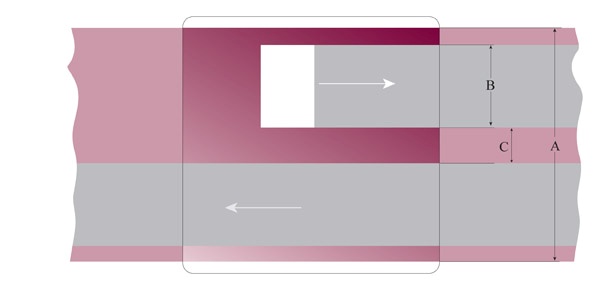
| A |
maximum recording width1 |
B | C | |
|---|---|---|---|---|
| Ampex |
6.3 mm, (0.248 in) |
6.05 mm (0.238 in) |
1.9 mm (0.075 in) |
2.14 mm (0.084 in) |
|
IEC 94-6 1985 2 track |
6.3 mm, (0.248 in) |
5.9 mm (0.232 in) |
1.95 mm (0.077 in) |
2.00 mm (0.079 in) |
| IEC home stereo (pre 1985) |
6.3 mm, (0.248 in) |
6.3 mm, (0.248 in) |
2.0 mm (0.079 in) |
2.25 mm (0.089 in) |
| NAB 1965 |
6.3 mm, (0.248 in) |
6.05 mm (0.238 in) |
2.1 mm (0.082 in) |
1.85 mm (0.073 in) |
|
IEC-1 Time code DIN mono half track |
6.3 mm, (0.248 in) |
6.3 mm, (0.248 in) |
2.3 mm (0.091 in) |
1.65 mm (0.065 in) |
|
IEC 94-6 1985 Stereo |
6.3 mm, (0.248 in) |
5.9 mm (0.232 in) |
2.58 mm (0.102 in) |
0.75 mm (0.03 in) |
|
IEC-1 Stereo (pre 1985) Mono half track |
6.3 mm, (0.248 in) |
6.3 mm, (0.248 in) |
2.775 mm (0.108 in) |
0.75 mm (0.03 in) |
|
IEC ½ inch |
12.6 mm (0.496 in) |
5.0 mm (0.197 in) |
2.5 mm (0.098 in) |
Fig 2. section 5.4 two track and half track head configuration and dimensions.
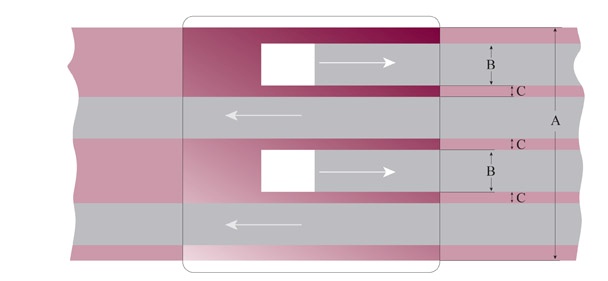
| A | B | C | |
|---|---|---|---|
|
IEC1 NAB |
6.3 mm, (0.248 in) |
1 mm (0.043 in) |
0.75 mm (0.43 in) |
Fig 3 section 5.4 quarter track head configuration and dimensions.
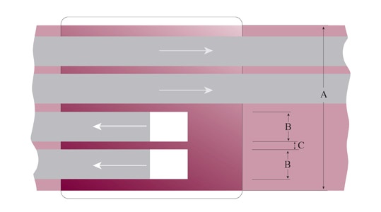
| A | B | C | |
|---|---|---|---|
|
IEC Philips |
3.81 mm, (0.15 in) |
0.6 mm (0.02 in) |
0.3 mm (0.012 in) |
Fig 4 Section 5.4 Stereo Cassette head configuration and dimensions.
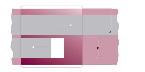
| A | B | |
|---|---|---|
|
ANSI Philips |
3.81 mm, (0.15 in) |
1.5 mm (0.06 in) |
Fig 5 Section 5.4 Mono Cassette head configuration and dimensions.
5.4.4.4 Head dimensions are specified in different ways in the European and US standards. Initially, the International Electrotechnical Commission (IEC), predominately referred to by European manufacturers, specified the tape with regard to the centre of the tape and the distance between the tracks, while the American based standards referred to the size of the recording track width defined diagrammatically with respect to one side. The size of the tape itself, has changed over time, initially a quarter of an inch, it was defined as 0.246 ± 0.002 inch (6.25 ± 0.05 mm) and later as 0.248 ± 0.002 in (6.3 ± 0.05 mm)”. IEC defines recording width in a full track recording in the following manner,”A single track shall extend over the whole width of the tape.” (IEC 94 1968:11), whereas the American based standards define the size of the recorded track to slightly less than the width of a 0.246 inch tape at 0.238 +0.010 -0.004 inch track size (this is a pragmatic solution to the problem of “grooves” in head wear and extends to all track dimensions). IEC later changed their full track width to 5.9 mm (0.232 inches). The number of standard track widths specified in figs.1 to 5 suggests that there is very little standardisation. (Eargle 1995, Benson 1988, IEC 94-1 1968, 1981, IEC 94-6 1985, NAB 1965 McKnight 2001, Hess 2001).
5.4.4.5 The net effect of replaying tapes on mismatched head widths is discussed in 5.4.2.2 above. It is important to attempt to assess the correct head width with which the original tapes were recorded and to then replay them on the most appropriate machine available. half” and 1” two track recordings are generally made in half track configuration only, and with specialised professional recording equipment with the intention of providing very high quality analogue audio. The same type and standard of equipment is required for replay, and an even closer attention to the detail of the record/replay standards.
5.4.4.6 Multitrack recordings range from domestic 1/4” standards to professional 2” and care must be taken to ensure the replay of those tapes is accurate. If time code has been recorded as part of the recording it must be captured and encoded in such a way that it may be used for later synchronisation (see 2.8 for file formats).
5.4.4.7 Tape machines should be capable of replaying signals with a frequency response of 30 Hz to 10 kHz ±1 dB, and 10 kHz to 20 kHz +1, -2 dB.
5.4.4.8 The equalisation on a reel replay machine should be capable of being aligned for replaying NAB or IEC equalisation, preferably being able to switch between them without re-alignment.
5.4.4.9 Wow and flutter unweighted better than 0.05% at 15 ips, 0.08% at 7.5 ips, and average variation from true speed better than 0.1%.
5.4.4.10 A professional archival reel machine should also have gentle tape handling characteristics so that it does not damage the tape during replay. Many of the early and middle generation studio machines depended on the robust characteristics of the modern tape carrier for their successful operation. These machines may cause damage to older tapes, or to long play tapes or thin tapes used for field recording.
1. Maximum recording width refers to the width measured from the outside edge of the outer tracks (see section 5.4.4.4)
5.4.5 Replay equipment: Professional Cassette Machines
5.4.5.1 Professional cassette replay machines are unavailable new. Also, the second hand market for professional cassette machines is not as strong as that for reel machines making it difficult to locate appropriate equipment. This represents a critical problem for sound archives, many of whose collections hold large numbers of recorded cassette tapes. Thus it should be a matter of priority for any collection with cassette tapes to seek out and acquire professional cassette replay machines. The characteristics that distinguish a professional machine from a domestic machine, apart from the replay specification, include solid mechanical construction, the ability to adjust replay characteristics and head azimuth, and the provision of balanced audio outputs. Many high quality audiophile machines provide some of the above characteristics. The characteristics of a suitable archival cassette replay machine include the following:
5.4.5.2 Replay speeds 17/8 ips (4.76 cm/s) (note that speeds of 15/16 ips and 3 ? ips may also be required for replay of specially recorded cassettes).
5.4.5.3 Variation from speed better than 0.3%.Wow and flutter weighted better than 0.1%.
5.4.5.4 Replay frequency response of 30 Hz to 20 kHz +2, -3 dB.
5.4.5.5 Ability to replay Type I, II, and IV cassettes (as required).
5.4.5.6 Most cassette machines will automatically select the correct replay equalisation by reading the holes or notches on the top of the cassette housing or shell to determine the tape type. A few machines do not read the notches but have a switch that the operator uses to select the appropriate equalisation. Type III cassettes may be problematic as they are enclosed in shells identical to Type I cassettes, while requiring the same replay equalisation curve as Type II cassettes.Where no explicit option to replay Type III has been provided by the playback machine, it may be necessary to use a deck with adjustable equalisation or to rehouse the tape in a Type II shell (see Section 5.4.12.5 Cassette Enclosures).
5.4.6 Maintenance
5.4.6.1 All equipment will require regular maintenance to keep it in working order. However, as analogue replay equipment is going out of production, it is necessary to make plans for spare parts as manufacturers will only maintain spare parts for a finite, and possibly short, period of time.
5.4.7 Alignment (equalisation below)
5.4.7.1 Analogue equipment requires regular alignment to ensure that it continues to operate within specification. It is recommended that heads and tape path be thoroughly cleaned every 4 hours of operation, or more frequently if required, using a suitable cleaning fluid such as isopropyl alcohol on all metal parts. Rubber pinch rollers should be cleaned with dry cotton buds or with cotton buds dampened with water as necessary. The older, original rubber pinch rollers can gradually become brittle if cleaned with alcohol, increasing wow and flutter. The new generation of polyurethane pinch rollers, generally coloured dark green, may dissolve if cleaned with alcohol. Heads and tape path to be demagnetised every 8 hours of operation, tape path and replay characteristics checked for alignment every 30 hours of use and equipment should receive a total alignment and check every 6 months.
5.4.7.2 In the same way that machines and tape are going out of production, suitable test tapes are likewise becoming difficult to obtain, and some are now unobtainable. It behoves the archivist to acquire enough open reel and cassette test tapes to manage the transfer of their collection.
5.4.8 Speed
5.4.8.1 Although speed correction is also possible in the digital domain, it is better to avoid such later digital correction and to carefully choose replay speed in the first transfer process, and to document chosen speed and justification. Tape recorders are very likely to have exhibited inaccurate speed characteristics due to fault, poor alignment, or in some cases, unstable power supply. Consequently no tape speed should be taken for granted.
5.4.9 Capstan-less Machines and Non-linear Speeds
5.4.9.1 Some early generation reel recording machines were designed to run without the control of the capstan and pinch roller, and consequently exhibit steadily increasing speed. If these tapes are played at a standard, unchanging speed, the resultant signal would decrease in pitch as the tape was replayed. To play the tape correctly the replay speed must change in the same manner as the recording speed. Some of the more recent replay machines, such as those made by Nagra or Lyrec, have incorporated a voltage driven external speed control which allows the operator to design a simple circuit with a curve that matches the speed of the original. Some of the last generation replay machines, such as the Studer A800 series, incorporated microprocessor control allowing for programmable manipulation of the speed, and others like the Lyrec Frida allowed the speed to be manipulated in the MIDI environment. However, care should be taken in assuming that the speed increase is linear. The early capstan-less machines were made cheaply and the speed varied according to the load on the reel, the speed increase is often less at the beginning or end of the tape where one or the other of the reels is full making a graph of the replay speed over time far from linear.
5.4.10 Replay Equalisation
5.4.10.1 The signal representation in most analogue audio formats is deliberately not linear in terms of frequency response. Correct replay, therefore, requires appropriate equalisation of the frequency response.
5.4.10.2 The most common of the equalisation standards for audio replay of analogue tape are as set out below (Table 1 Section 5.4). It should be noted that equalisations have developed over time. The current standards are given in bold type, together with their date of introduction. Earlier recordings must be replayed by applying the respective historical standards and simple additional circuits may be utilised. The overlapping of old and new standards should be taken into account when decisions are to be made for tapes recorded in times of transition. Prior to that there were a number of manufacturers’ standards.
| 30 ips, 76 cm/s |
IEC2 AES |
(1981) current standard | ∞ | 17.5 μs |
| 30 ips, 76 cm/s |
CCIR IEC1 DIN |
(1953–1966) (1968) (1962) |
∞ | 35 μs |
| 15 ips. 38 cm/s |
IEC1 CCIR DIN BS |
(1968) current standard (1953) (1962) |
∞ | 35 μs |
| 15 ips. 38 cm/s |
NAB EIA |
(1953) current standard 1963 |
3180 μs | 50 μs |
| 7½ ips, 19 cm/s |
IEC1 DIN(studio) CCIR |
(1968) current standard 1965 1966 |
∞ | 70 μs |
| 7½ ips, 19 cm/s |
IEC 2 NAB DIN(home) EIA RIAA |
(1965) current Standard (1966) (1963) (1968) |
3180 μs | 50 μs |
| 7½ ips, 19 cm/s |
Ampex (home) EIA (proposed) |
(1967) | ∞ | 50 μs |
| 7½ ips, 19 cm/s |
CCIR IEC DIN BS |
(up to 1966) (up to 1968) (up to 1965) |
∞ | 100 μs |
| 3¾ ips 9.5 cm/s |
IEC2 NAB RIAA |
(1968) current standard (1965) (1968) |
3180 μs | 90 μs |
| 3¾ ips 9.5 cm/s | DIN | (1962) | 3180 μs | 120 μs |
| 3¾ ips 9.5 cm/s | DIN | (1955–1961) | ∞ | 200 μs |
| 3¾ ips 9.5 cm/s |
Ampex (home) EIA (proposed) |
(1967) | ∞ | 100 μs |
| 3¾ ips 9.5 cm/s | IEC | (1962–1968) | 3180 μs | 140 μs |
| 3¾ ips 9.5 cm/s | Ampex | (1953–1958) | 3180 μs | 200 μs |
| 17/8 ips 4.75 cm/s |
IEC DIN |
(1971) current standard (1971) |
3180 μs | 120 μs |
| 17/8 ips 4.75 cm/s |
IEC DIN RIAA |
(1968–1971) (1966–1971) (1968) |
1590 μs | 120 μs |
|
17/8 ips 4.75 cm/s cassette |
IEC Type I | 1974 current standard | 3180 μs | 120 μs |
|
17/8 ips 4.75 cm/s cassette |
DIN Type I | (1968–1974) | 1590 μs | 120 μs |
|
17/8 ips 4.75 cm/s cassette |
Type II and IV | (1970) Current standard | 3180 μs | 70 μs |
| 15/16 ips 2.38 cm/s | undefined |
Table 1 Section 5.4 Common Equalisation Standards for Audio Replay of Analogue Tape4
5.4.10.3 At 15 ips and 7.5 ips there is a choice in replay equalisation for reel tapes even for tapes which were recently recorded according to the current standards. However, these are the two most common recording speeds, and care must be taken when choosing a replay equalisation to ensure that it corresponds with the record equalisation. Apart from the standards mentioned in table 1 section 5.4 there are a small number of more current standards intended to achieve better performance but which are different from the commonly accepted standards. At 15 ips Nagra tape recorders have the option to use a special equalisation called NagraMaster. The US version of NagraMaster had time constants ∞ and 13.5 µs, the European version of NagraMaster had time constants 8 and 13µs. Ampex used “Ampex Master Equalization” (AME), also at 15 ips but officially only on particular 1/2 inch mastering recorders introduced in 1958 and sold for several years following (MRL 2001). Logging machines and some popular semi-professional portable equipment were able to record at the very slow speed of 15⁄16 ips (2.38 cm/s). However, it appears that there is no agreed exchange standard for these tapes and any equalisation would have adhered to proprietary conventions.
5.4.10.4 Sometimes any lack of documentation may require the operator to make replay equalisation decisions aurally. Cassette replay equalisation corresponds to the tape type, and care must be taken to ensure that the correct replay equalisation is used. Many tape recordings, specifically private recordings and those of cultural or research institutions that lacked technical support, have been made on un-aligned tape recorders. Unless there is objective evidence that would allow alternate settings, with regard to equalisation, tapes must be treated as properly aligned.
4. Note, IEC refers to IEC Pub 60094-1 4th edition, 1981, NAB to the NAB reel to reel standard 1965 (IEC2), or cassette standard 1973, DIN refers to DIN 45 513-3 or 45 513-4 and AES to AES-1971, and BS to the British Standard BS 1568). Thanks to Friedrich Engel, Richard L. Hess and Jay McKnight for generously supplying information on tape equalisation.
5.4.11 Noise Reduction
5.4.11.1 The signal recorded onto a tape may have been encoded in such a way as to mask the inherent noise of the carrier. This is known as noise reduction. If the tape has been encoded while recording, it must be decoded using the same type of decoder appropriately aligned. The most common noise reduction systems include Dolby A, and Dolby SR (professional), Dolby B and Dolby C (domestic), dbx types I (professional) and II (domestic)although rarely used and TelCom.
5.4.11.2 The alignment of the record and replay characteristics of the tape machine are critical to the adequate operation of noise reduction systems and characteristic line up tones are often included on professionally recorded tapes. The output level, as well as the frequency response can alter the response of the decoding system and it is also important to note that noise reduction may be applied to either IEC or NAB equalisation and must be replayed correctly. Dolby B and Dolby C have routinely been included in most professional cassette decks of recent years and generally do not have line up tones and have a less obvious effect on the signal than the professional systems.
5.4.11.3 Though it is possible to transfer the audio from an encoded tape for decoding at a later time, the multiple variables in alignment can compound the errors and make it difficult to decode accurately once the tape has been transferred. Decoding is better undertaken at the time of transfer.
5.4.11.4 Unless documented, it is difficult to assess whether compact cassettes have encoded with a noise reduction system. As with equalisation, the lack of documentation may require the operator to make such decisions aurally. The right replay is generally characterised by an even level of background hiss, while the fluctuation of this level indicates a wrong playback setting. A spectrum analysis tool can be helpful. If it cannot be determined, copies of cassettes should be made flat.
5.4.12 Corrections for Errors Caused by Misaligned Recording Equipment
5.4.12.1 Misalignment of recording equipment leads to recording imperfections, which can take manifold form.While many of them are not, or hardly correctable, some of these faults can objectively be detected and compensated for. It is imperative to take compensation measures in the replay process of the original documents incurred, as no such correction will be possible once the signal has been transferred to another carrier.
5.4.12.2 Azimuth and Tape Path Alignment: Inaccurate alignment of the record head of the original recording machine means that at replay, the signal retrieved will exhibit a reduced high frequency response, and, in the case of two or more track replay, an altered phase relationship between the two channels. Adjustment of the angle of the replay head such that the relationship of the head is in the same plane as the magnetised field on the tape is termed the azimuth adjustment and this simple adjustment can markedly improve the quality and intelligibility of the retrieved signal. There is no difficulty in training staff in this task, and good binaural hearing is all the measuring technology required. An accurate phase meter or oscilloscope will aid in the adjustment of mono and properly recorded tapes, they may, however, be misleading on tapes recorded on cheap, domestic equipment. In such cases aural judgement of the high frequencies should be relied on. Additionally or alternatively, a software programme providing a real time-spectrogram function can be used. Azimuth adjustment should be a routine part of all magnetic tape transfers.
5.4.12.3 Digital systems may correct the phase relationship of the signal (often described as azimuth correction), however such procedures cannot retrieve the high frequency information that is lost. Azimuth adjustments must be made on the original tape before transfer commences.
5.4.12.4 The vertical alignment of the heads on the original recording machine may present an obstacle to the appropriate reproduction of the signal. This is particularly the case with recordings made on amateur or consumer-grade equipment. In order to obtain a visual representation of the alignment of the tracks on the tape of a recording the following procedure should be followed: Recorded portions of tapes should be protected by a very thin transparent sheet of Mylar or similar transparent material. A powder or suspension of ferromagnetic material, particle size less than 3 µm, is sprayed over the transparent sheet. The magnetic properties of the recorded portion of the tape then make the tracks visible. A carefully marked series of measurement lines on the sheet will aid in detecting misalignment. These tape path adjustments are less frequently required than azimuth adjustment, but if they must be undertaken the replay equipment should be recalibrated by a qualified technician. Every care should be taken to ensure no iron particles remain in contact with the tape as these may damage the replay heads.
5.4.12.5 Cassette Enclosures: The enclosures in which low cost cassette tapes are housed may cause the tape to jam or replay with increased wow and flutter. In such cases it is often beneficial to replace the tape in a high quality screwed enclosure being sure to include the rollers, pressure pad and lubricating sheets.
5.4.12.6 Wow, Flutter and Periodic Tape Speed Variations: There is little that can be done to effectively improve periodic variations in the recorded signal. It is therefore imperative that the replay equipment is thoroughly and carefully checked, aligned and maintained to ensure that no speed related artefacts are introduced.With the availability of high resolution A/D converters and components, it seems possible to retrieve the high frequency (HF) bias signal from analogue magnetic tapes during transfer, which may enable the correction of wow and flutter. There are, however, many significant barriers to realising this, including a lack of available hardware to extract signals of such high frequencies and the inherent unreliability of the bias signal itself. As the procedure is generally time-consuming and complex, and substantial improvements concerning this matter are not to be expected, implementation is unlikely, and even then, only feasible for a limited group of tapes produced under specific circumstances.
5.4.13 Removal of Storage Related Signal Artefacts
5.4.13.1 It is preferable in most cases to minimise the storage related signal artefacts before undertaking digitisation. In linear analogue magnetic recording, for example, print-through is a well-known and disturbing phenomenon. The reduction of this unwanted signal can only be undertaken on the original tape.
5.4.13.2 Print-Through: Print-through is the unintentional transfer of magnetic fields from one layer of analogue tape to another layer on the tape reel. It reveals itself as the pre and post echoes to the main signal. The intensity of print through signal is a function of the wavelength, tape coating thickness, but primarily the spread of the coercivity5 of the particles in the magnetic layer. Almost all print through occurs soon after the tape is recorded and wound onto the pack. The increase in print-through after this reduces over time. Further significant increases in print-through occur only as a consequence of changes in temperature. When the tape is stored with the oxide facing in to the hub, the most common standard, the print on the layer outside of the intended signal is stronger then the print signal on the layer towards the hub of the spool. Consequently it has been frequently recommended that tapes be stored “tail out”, in which case the post echoes are louder than the pre echoes and less obvious. German broadcast standards specified that tapes be wound with the oxide out, in which case the reverse applies, and tapes should be stored “head out”.
5.4.13.3 Printed signals are reduced by the act of rewinding the tape prior to playing, by a process termed “magnetostrictive action”. Systematic tests have shown, however, that it is wise to rewind a tape at least three times to sufficiently diminish print through (Ref Schuller 1980). If the printed signal is very high and it does not respond adequately to rewinding, some tape machines allow the application of a low level bias6 signal to the tape during playback. This selectively erases lower coercivity particles and hence reduces print-through, though it may also have an effect of the signal, especially if over-applied, and should only be used as a last resort and then very carefully.
5.4.13.4 Though print-through can be reduced on the original tape the same level of restoration is not achievable afterwards. Once copied to another format the printed signal becomes a permanent part of the wanted signal.
5.4.13.5 Vinegar Syndrome and Brittle Acetate Tape: Acetate tape becomes brittle with age which may make it difficult to play a tape without breaking. The brittleness occurs as a result of a process of chemical degradation which occurs when the molecular bonds of the acetate compound break down to release acetic acid giving off the characteristic smell of vinegar. Broken acetate tape can be spliced without any signal loss or deterioration, because, as a result of its brittleness, no elongation of the tape occurs. Brittle tapes, however, are also subject to a variety of deformations which hinder the necessary tape-to-head contact for optimal signal retrieval. Though a process of re-plastification would be advantageous,such processes do not exist as yet. Archivists are warned against the chemical processes sometimes suggested as these may not only jeopardise the further survival of the tape,but also contaminate replay equipment and, indirectly, other tapes replayed on such machines. Instead, it is recommended that such tapes be replayed using a recent machine that permits to lower tape tension. This will enable an acceptable compromise between care of the fragile tape and the application of enough tape tension to permit the best possible tape-to-head contact.
5.4.13.6 Physical Tape Memory: Poorly stored and spooled polyester and PVC tapes may also suffer from deformation of the tape. The tape will often retain a memory of that deformation and so make poor tape to head contact, which reduces the signal quality. Repeated respooling and resting may reduce some of this effect.
5. Coercivity; A measure of the intensity of the magnetic field needed to reduce the magnetization of a ferromagnetic material to zero after it has reached saturation
6. Bias; A high frequency signal mixed with the audio during recording to help reduce tape based noise. Devised by Weber in 1940
5.4.14 Wire Recordings
5.4.14.1 Though the principles of wire recordings were demonstrated at the very end of the 19th century, and various dictation machine manufacturers produced working models in the 1920s and 1930s (see 5.4.15 below), it was not until around 1947 that the wire recorder was successfully marketed to the general public.
5.4.14.2 The speed of wire recorders was not standard and varied between manufacturers and even, on occasion, from model to model. After 1947, however, manufacturers mostly adhered to a standard speed of 24 ips and a reel size of 2¾ inches. Wire recorders did not have capstans, and so the speed would change as the take up reels became full. The size of the take up spool was integral to the correct replay of the wire, and very often related to a particular machine or manufacturer. The take-up spool is generally a fixed part of the machine. The height of popularity of the wire recorder was in the years from the mid 1940s till the early 1950s, a period which coincided with the development and introduction of the technically superior tape recorder and the wire was soon considered obsolete. Even in its heyday, the wire recorder was primarily used as a domestic recorder, though some were used for commercial purposes.
5.4.14.3 Though the wire fell quickly from favour, wires were available in speciality outlets until the 1960s. Early reel sizes were large in comparison to the 2¾ inch reels which become the most commonly used reel. Some wires, mostly early in the history of the wire recorder, were made from plated or coated carbon steel, and these may now be corroded and difficult to play. Many wires, however, are in excellent condition being made from Stainless Steel with 18% chromium and 8% nickel, and have not corroded.
5.4.14.4 The principle of wire recorders is comparatively simple, so that the construction of a replay machine is possible. However, the complexity associated with successfully spooling and playing the fine wire without tangles or breakages suggest that the best approach to replay is to use an original machine, though it is worth noting that some experts have modified tape machines to replay wires.When using original machines it is recommended that the audio electronics be overhauled to ensure best performance or, preferably, replaced with audio circuitry using modern components (Morton 1998, King: n.d.)
5.4.15 Magnetic office dictation formats
5.4.15.1 In the decades following World War II a wide variety of magnetically recorded office dictation formats appeared. That the needs of the office differ from other audio recording environments is reflected in their design: reduced size and weight, ease of operation and variable speed were prioritised, usually at the expense of audio quality. Magnetic dictation systems may be broadly divided into tape and non-tape-based formats.
5.4.15.2 Tape in this context includes various forms of wire (see 5.4.14 above), reel and cassette. Some formats may be playable using standard equipment (non-standard cassette formats may sometimes be rehoused and replayed in standard cassette shells for instance) while others may only be played on dedicated format-specific players. Where a choice is available, a decision needs to be made between the two approaches. One entails the use of high- specification, relatively easy to maintain standard equipment, potentially coupled with poor compatibility in tape width, head configuration, replay speed, equalisation, noise reduction etc. The other offers higher compatibility between carrier and player, but very likely at the cost of the lower specification and esoteric maintenance needs of the original format-specific equipment. Tape-based formats can be subdivided into linear and non¡linear speed. The former will present fewer problems if replayed on conventional equipment; the latter may also be playable in this way, but will require speed adjustment (see 5.4.9).
5.4.15.3 Non-tape formats include a bewildering array of discs, belts, rolls and sheets, all featuring magnetically coated surfaces, recorded onto and replayed using heads similar in principle to conventional tape heads. Given sufficient expertise, time and money therefore, it may be possible to build replay devices for some of these formats, incorporating components from more common tape replay equipment. In many cases however locating an original replay machine might be more feasible, and it may be possible to contract a specialist equipped to carry out the work.
5.4.16 Time Factor
5.4.16.1 The time needed for copying contents of audio material varies greatly, and is highly dependent on the nature and status of the original carrier. The step of actually playing the carrier is only one part of the process, which includes respooling, assessment, adjustment and documentation. Even a well documented, good quality analogue tape of 1 hour’s duration will take, on average, twice the time of the length of its recording to properly transfer to a digital carrier. In the mid-1990s the Archivarbeitsgruppe of ARD (Arbeitsgemeinschaft der Rundfunkanstalten Deutschlands) would regard this as optimistic as they postulated a transfer factor of 3 (1 operator: 3 hours of work for 1 hour of material) for the transfer of typical archival holdings of their radio stations. Tapes that exhibit any faults, which require repair or restoration, or need documentation or the assessment and addition of metadata, will take much longer to conserve, transfer and preserve.
5.4.17 Signal Auto detection, auto upload (failings and benefits)
5.4.17.1 It is recommended that all tapes be actively listened to while preservation transfers are being undertaken. However, in response to the sheer quantity of the material to be transferred and preserved, manufacturers of digital archiving systems have been developing ways of automatically monitoring and detecting signal faults allowing for the possibility of unattended transfers. The savings in time are obvious, as an individual operator may undertake multiple transfers simultaneously. The systems themselves seem to achieve their greatest benefit on largely homogenous collection material that is well recorded on stable carriers that can be treated identically. This is evident in that the most successful mass upload systems have been undertaken or implemented by broadcast archives where the content is largely of similar quality, the collection size is large, and the resources are available to build, manage and run such systems. For material that requires individual treatment, and this is typified in most research and heritage collections, the benefits of an automated system are not as great.
5.5 Reproduction of Digital Magnetic Carriers
5.5.1 Introduction
5.5.1.1 Under optimum conditions digital tapes can produce an unaltered copy of the recorded signal, however any uncorrected errors in the replay process will be permanently recorded in the new copy or sometimes, unnecessary interpolations will be incorporated into the archived data, neither of which is desirable. Optimisation of the transfer process will ensure that the data transferred most closely equates to the information on the original carrier. As a general principle, the originals should always be kept for possible future re-consultation however, for two simple practical reasons any transfer should extract the optimal signal from the best source copy. Firstly, the original carrier may deteriorate, and future replay may not achieve the same quality, or may in fact become impossible, and secondly, signal extraction is such a time consuming effort that financial considerations call for an optimisation at the first attempt.
5.5.1.2 Magnetic tape carriers of digital information have been used in the data industry since the 1960s, however, their use as an audio carrier did not become common until the early 1980s. Systems reliant on encoding audio data and recording onto video tapes were first used for two track recording or as master tapes in the production of Compact Discs (CD). Many of these carriers are old in technical terms and in critical need of being transferred to more stable storage systems.
5.5.1.3 A crucial recommendation of all transfers of digital audio data is to carry out the entire process in the digital domain without recourse to conversion to analogue. This is relatively straightforward with later technologies which incorporate standardised interfaces for exchanging audio data, such as AES/ EBU or S/PDIF standards. Earlier technologies may require modification to achieve this ideal.
5.5.2 Selection of Best Copy
5.5.2.1 Unlike copying analogue sound recordings, which results in inevitable loss of quality due to generational loss, different copying processes for digital recordings can have results ranging from degraded copies due to re-sampling or standards conversion, to identical “clones” which can be considered even better (due to error correction) than the original. In choosing the best source copy, consideration must be given to audio standards such as sampling and quantisation rate and other specifications including any embedded metadata. Also,data quality of stored copies may have degraded over time and may have to be confirmed by objective measurements. As a general rule a source copy should be chosen which results in successful replay without errors, or with the least errors possible.
5.5.2.2 Unique Recordings: Original source materials such as multi-track sessions, field recordings, logging tapes, home recordings, sound for film or video, or master tapes, may include unique content in whole or in part. Un-edited material may be less or more useful than the edited final product, depending on the purpose of the archived material. Curatorial decisions must be made to ensure that the most appropriate or complete duplicate is selected. Truly unique recordings do not present any choice to the archivist. In the case where content is uniquely held on a single copy within a collection it is worth considering whether alternative copies might exist elsewhere. It may be possible to save both time and trouble if other copies exist which are in better condition, or on a more convenient format.
5.5.2.3 Recordings with Multiple Copies: Preservation principles indicate that copies of digital tape should ideally be a perfect record of the media content and any associated metadata as recorded on the original digital document. Any digital copy meeting this standard is a valid source for migration of the essence to new digital preservation systems.
5.5.2.4 In reality, effects of standards conversion, re-sampling or error concealment or interpolation1 may result in data loss or distortion in copies, and deterioration over time degrades the quality of original recordings and subsequent copies. As a result, copying outcomes may differ depending on the choice of source material. Cost can also vary depending on the physical format or condition of the source material.
5.5.2.5 Determining the best source copy requires consideration of recording standards used to create copies, quality of equipment and processes used, and the current physical condition and data quality of available copies. Ideally this information is documented and readily available. If this is not so then decisions must be based on understanding of the purpose and history of various copies.
5.5.2.6 Duplicates on Similar Media: Best source material in this case will be that copy with the best data quality. First choice will usually be the most recently made unaltered digital copy. Earlier generations of unaltered digital copies may represent an alternative if the newer copies are inadequate due to deterioration or improper copying.
5.5.2.7 Copies Differing in Media or Standard: Production or preservation processes may result in availability of multiple copies on differing digital tape formats. The best source material should be identical to the original in standard, have the best available data quality, and be recorded on the most convenient format for reproduction. Judgment is called for if any of these conditions cannot be met.
5.5.2.8 If the digital recordings are only duplicates of analogue recordings, and where the analogue originals still exist, re-digitisation is an option to consider if those digital copies are inferior in standard, quality or condition.
1. Error concealment or interpolation is an estimation of the original signal when data corruption prevents accurate re-construction of the signal.
5.5.3 Cleaning, Carrier Restoration
5.5.3.1 Magnetic digital tapes are similar in materials and construction to other magnetic tapes, and suffer from similar physical and chemical problems. Digital tapes achieve high data densities through the use of thin tapes, small magnetic tracks and ongoing reductions in the size of the magnetised domains which can be written and read. Consequently even minor damage or contamination can have major impacts on signal retrievability. All tape degradation,damage or contamination will appear as increased errors. Carrier restoration problems and techniques are similar for all magnetic tapes, but since base, binder and magnetic materials are subject to ongoing development any restoration processes must be tested and proven for specific media.
5.5.3.2 Commercial cleaning machines are available for open reel magnetic tapes and for most videotape formats commonly used to carry digital audio signals and are effective for moderately degraded or contaminated tapes.Vacuum or hand cleaning may be indicated for tapes with higher levels of contamination or of greater fragility, but requires conservatorial care to avoid damaging delicate tapes and intricate cassette mechanisms. Any cleaning process has potential to cause damage and should be applied with appropriate caution.
5.5.3.3 Jigs can aid in manipulating tapes and cassette housings, and are commercially available for some formats. Purpose-built jigs for other formats can be manufactured in a moderately well equipped mechanical workshop.
5.5.3.4 Digital tapes with polyester urethane binders have the potential to suffer from hydrolysis in the same way as analogue magnetic tapes. Any rejuvenation of digital magnetic tape will require tight process control, and should only be attempted in a purpose-built environmental chamber or vacuum oven2 (see Section 5.4.3 Cleaning and Carrier Restoration). This may be even more critical with digital recordings as they will often have been made on thinner based tapes housed in complex cassette mechanisms.
5.5.3.5 Deterioration of magnetic tapes can be minimised by appropriate storage conditions. Standards for long-term digital magnetic tape storage are generally more stringent than for analogue tapes, due to their greater fragility and susceptibility to data loss through relatively minor damage or contamination. Higher than recommended temperature or humidity will promote chemical deterioration. Cycling of temperature and humidity will result in expansion and contraction of the tape and may damage the tape base. Dust or other contaminants can find its way onto the tape surface resulting in data loss and possibly physical damage during replay.
5.5.3.6 After cleaning and/or repairing measures or prior to the reproduction it may be advisable to first measure the magnetic digital tape’s error rates. The organisation of the data and the type of error correction used varies according to the tape format. For DAT for example, the error correction process uses two Reed-Solomon codes arranged in a cross code system, C2 horizontally and C1 vertically. Also, each block of data has a value assigned, known as a parity byte. Counting the Block parity errors are known as CRC errors, or sometimes as the block error rate. The sub code of the DAT (Digital Audio Tape) is also subject to errors. Error measurement should include, as a minimum:
5.5.3.6.1 C2 and C1 errors.
5.5.3.6.2 CRC or Block error rate.
5.5.3.6.3 Burst Errors (derived from C1).
5.5.3.6.4 SUBC1 correction.
5.5.3.7 If any of the error measurement reveals a sample hold, interpolated or mute level error the tape should be cleaned and the tape path checked. If after cleaning and repair one or more of the error rates exceed these thresholds refer to 5.6.3 “Selection of Best Copy.” (above).
5.5.3.8 There are very few error measuring devices available for DAT or other magnetic carriers. Any transfer, however, should include a measurement of the errors produced at the error correction chip of the replay machine and this information must be recorded in the metadata of the resultant audio file.
2. Vacuum ovens reduce the air pressure in the oven chamber and so better control moisture content
5.5.4 Replay Equipment
5.5.4.1 Replay equipment must comply with all specific parameters of a given format. Digital tape formats are mostly proprietary in nature, with only one or two manufacturers of suitable equipment. Latest generation equipment is preferred, but for older or obsolete digital formats there may be no choice but to purchase second- hand equipment.
5.5.4.2 The high recording density of R-DAT(Rotary Head Digital Audio Tape) has ensured that applications other than audio-recording-only were developed. The DDS (Digital Data Storage) format, based on DAT technology, was developed by Hewlett-Packard and Sony in 1989 and was dedicated to the storage of computer data. Steady increases in data integrity of the basic system resulted in developments which allow for signal extraction from audio DAT tapes.Various types of software are available which allow the extraction of the audio as separate files based on ID’s on the tape. Dedicated data extraction software can also generate metadata files for each program, including clock, start and end ID positions, durations, file size, audio properties, etc. Additionally the DDS format allows double speed capturing of audio material.
5.5.4.3 Nevertheless, the important questions such as format incompatibilities (e.g. the different long play modes, high resolution recordings, time code extraction etc.), proper data integrity checking, pre-emphasis handling and especially all matters concerning mechanical and tracking problems are still not yet solved by such systems and therefore need individual treatment.
5.5.5 Common Systems and Characteristics: Cassette Systems
5.5.5.1 The R-DAT (commonly referred to as DAT) is the only common system to use a cassette format specifically developed for digital audio recordings. DAT tapes have been widely used in field and studio recording, broadcasting and archiving. New DAT equipment is now virtually unavailable. Second hand professional DAT machines are a solution, but present maintenance problems as parts supplies become exhausted.
5.5.5.2 Some last generation recorders operate outside the specification, allowing high resolution recording at 96 kHz and 24 bits (at double speed), others provided Timecode (SMPTE) recording, or Super Bit Mapping, a psycho-acoustic principle and critical band analysis to maximize the sound quality of 16-bit digital audio. 20-bit recordings are quantized to 16 bits using an adaptive error-feedback filter. This filter shapes the quantization error into an optimal spectrum as determined by the short-term masking and equi-loudness characteristics of the input signal. Through this technique, the perceptual quality of 20-bit sound is available on a 16-bit DAT recording. Full quality can only be reached with signals containing frequencies lower than 5-10 kHz. Super bit mapping does not require special decoding on playback.
|
Record/playback mode |
Pre-recorded tape (Playback only) |
||||||
|---|---|---|---|---|---|---|---|
| Standard | Standard | Option 1 | Option 2 |
Option 3 | Normal track | Wide Track | |
| Number of Channels |
2 | 2 | 2 | 2 | 4 | 2 | 2 |
| Sampling rate (kHz) |
48 | 44.1 | 32 | 32 | 32 | 44.1 | |
| Number of quantization bits |
16 (linear) | 16 (linear) | 16 (linear) | 12 (non linear) |
12 (non linear) |
16 (linear) | |
| Linear recording density (KBPI) |
61.0 | 61.0 | 61.1 | ||||
| Surface recording density (MBPI2) |
114 | 114 | 76 | ||||
| Transmission rate (MBPS) |
2.46 | 2.46 | 2.46 | 1.23 | 2.46 | 2.46 | |
| Sub-code capacity (KBPS) |
273.1 | 273.1 | 273.1 | 136.5 | 273.1 | 273.1 | |
| Modulation | 8–10 Conversion | ||||||
| Correction | Dual Reed Solomon | ||||||
| Tracking | Area split ATF | ||||||
| Cassette size (mm) | 73x54x 10.5 | ||||||
| Recording time* (min) |
120 | 120 | 120 | 240 | 120 | 120 | 80 |
| Tape width (mm) | 3.81 | ||||||
| Tape type | Metal-particle | Oxide | |||||
| Tape thickness (μm) |
13±1μ | ||||||
| Tape speed (mm/s) | 8.15 | 8.15 | 8.15 | 4.075 | 8.15 | 8.15 | 12.225 |
| Track pitch (μm) | 13.591 | 13.591 | 20.41 (wide track) |
||||
| Track angle | 6°22’59”5 | 6°23’29”4 | |||||
| Standard drum | Ø 30 90° Wrap | ||||||
| Drum revolution speed (r.p.m.) | 2000 | 1000 | 2000 | 2000 | |||
| Relative speed (m/s) |
3.133 | 1.567 | 3.129 | 3.133 | 3.129 | ||
| Head azimuth | ±20° | ||||||
Table 1 Section 5.5 Specifications for various record/playback modes of DAT for both blank and pre-recorded tapes:
5.5.5.3 Phillips DCC (Digital Compact Cassette) system was (unsuccessfully) introduced as a consumer product and offered limited compatibility with analogue compact cassettes through the ability to replay analogue cassettes on DCC equipment. DCC is now considered obsolete.
| Format | Variants | Carrier Type | Audio and data tracks | Digital Audio Standards supported | Interface |
|---|---|---|---|---|---|
| DAT or R-DAT | Timecode is not part of the R-DAT standard but may be implemented in Sub-Code. Some pre-recorded DATS use ME tape | Cassette with 3.81mm metal particle tape. | Stereo. Subcode includes standardised markers plus user bits for proprietary extensions | 16 bit PCM @ 32, 44.1 and 48 kHz | AES-422 on professional machines. SP-DIF standard |
| DCC | Cassette with 3.81 CrO2 | Stereo, metadata standard supports minimal descriptive data | PASC compressed PCM (4:1 bit rate reduction) | ||
| Videotape based formats — see table 4 |
Table 2 Section 5.5 Digital Audio Cassettes
5.5.6 Common Systems and Characteristics: Open Reel Formats
5.5.6.1 SONY and Mitsubishi have both produced open reel digital systems for the recording studio market, and NAGRA produced a four-track field recording system, the NAGRA-D.
5.5.6.2 Sony/Studer’s DASH (Digital Audio Stationary Head) system has numerous variants, based on common formats for the digital tracks on tape. DASH I provides 8 digital tracks on ¼” tape and 24 digital tracks on ½" tape. DASH-II provides 16 digital tracks on ¼” tape and 48 tracks on ½" tape. Twin DASH formats are commonly used for ¼” stereo digital recordings and utilise twice the normal number of data tracks for each audio channel to increase the systems error correction capability so that tape splicing can be used for editing. Low speed formats double recording time by sharing data for each audio channel across multiple data tracks, halving the number of audio tracks available.
5.5.6.3 Nagra still support NAGRA-D Sony DASH and Mitsubishi Pro-Digi format machines are no longer manufactured. These formats are/were intended for high-end professional use and as a result were extremely expensive to support.
| Format | Variants | Carrier Type | Audio and data tracks | Digital Audio Standards supported | Interface |
|---|---|---|---|---|---|
| DASH | Three speeds – F (fast), M (medium) and S (slow) | ¼” or ½” tape | Up to 48 audio tracks plus control track | 16 bit at 32 kHz, 44.1 kHz or 48 kHz | AES/EBU SDIF-2 MADI interface |
| DASH-I (single density) and DASH-II (double density) | |||||
| Two tape widths Q (quarter inch) and H (half Inch) | |||||
| Mitsubishi Pro Digi | Stereo | ¼” tape | 32 kHz, 44.1 kHz or 48 kHz. 20 bit or 16 bit (with extra redundancy to facilitate splice editing) at 15 ips. 16 bit (normal redundancy) at 7.5 ips | AES/EBU or proprietary multi-channel interface | |
| 16 track | ½” tape | 32 kHz, 44.1 kHz or 48 kHz. 16 bit | |||
| 32 track | 1” tape | 32 kHz, 44.1 kHz or 48 kHz. 16 bit | |||
| NAGRA-D | ¼” MP | 4 audio tracks. Extensive metadata including TOC and built-in error recording | 4 tracks at up to 24 bit 48 kHz 2 tracks at 24 bit 96 kHz | AES/EBU |
Table 3 section 5.5 Open Reel Formats
5.5.7 Common Systems and Characteristics: Video Tape Based Formats
5.5.7.1 There are two variants within this category: systems using videotape in a standard VCR to record digital audio encoded on a standard video signal, and systems using videotape as the storage medium for proprietary digital audio signal formats.
5.5.7.2 Sony has produced a range of formats using VCR systems as a high bandwidth storage device. More recently Alesis introduced the ADAT system, which used S-VHS videocassettes as high capacity storage media for their proprietary format of digital audio, and Tascam released the DTRS system using Hi8 videocassettes as the storage medium.
5.5.7.3 Formats using video recorders were based on interface devices that incorporated A-D and D-A converters, audio controls and metering, and the hardware required to encode the digital bit stream as a video waveform. Sony’s professional system specified NTSC standard (525/60) Black-and-White U-Matic VCR, and these were manufactured specifically for digital audio use. The semi-professional PCM-F1, 501 and 701 series worked best with Sony Betamax recorders, but were generally compatible with Beta and VHS. Machines in this series supported PAL, NTSC and SECAM standards.
5.5.7.4 Reproduction of VCR based recordings requires availability of a VCR of the correct standard, plus the appropriate proprietary interface. There is normally backwards compatibility within related systems, so purchase of later generation equipment should facilitate replay of the widest range of source material. As some of the video based PCM adaptors had only one A/D converter for both stereo channels, there is a time delay between the two channels.When the tapes are replayed and the audio data is extracted the signal processor delay should be corrected in the digital domain. Transfers should be made only with equipment which allows the output of a digital signal.
5.5.7.5 Early digital recorders sometimes encoded in what are now uncommon sampling rates, such as 44.056kHz (see table 4 Section 5.5). It is recommended that the resultant files be stored at the encoding levels at which they were created. Care should be taken to ensure that automatic systems do not misrecognise the actual sampling rate (eg a 44.056kHz audio stream may be recognised as 44.1kHz, which alters the pitch and speed of the original audio). Second files can be created for users in common sampling rates using appropriate sampling rate conversion software. Nonetheless, the original file should be retained.
5.5.7.6 In addition, third-party equipment for systems based on domestic VCRs can provide useful extended functionality, including better metering and error monitoring facilities and professional inputs and outputs.
5.5.7.7 VCR based systems are obsolete, and equipment will need to be sourced second-hand.
| Format | Variants | Carrier Type | Audio and data tracks | Digital Audio Standards supported | Interface |
|---|---|---|---|---|---|
| EIAJ Sony PCM-F1 PCM-501 and PCM-701 systems | Video signal may be PAL, NTSC or SECAM | Domestic VCR — normally Betamax or VHS cassette Rare examples use ½” open reel videotape | Stereo Audio | 14 bit standard, Sony hardware allows 16 bit sampling (with less error correction) 44.056 kHz in NTSC systems, 44.1 kHz in PAL systems | Analogue line in and out standard. Digital I/O capability with third party add-ons |
| Sony PCM1600 PCM1610 and PCM1630 | U-Matic – Black and White, 525/60 (NTSC) | Stereo audio plus Compact Disc PQ codes Timecode on U-matic linear audio track | 16 bit 44.1 kHz | Sony proprietary system. Digital audio on separate Left and Right Channels plus word-clock | |
| DTRS (1991) | Proprietary format on Hi8 video cassettes | 16 bit 48 kHz 20 bit recording optional on some systems | SP-DIF or AES/ EBU | ||
| ADAT (1993) | Proprietary system on S-VHS cassettes | SP-DIF or AES/ EBU |
Table 4 section 5.5 Digital Audio on Videotape – Common Systems
5.5.8 Replay Optimisation
5.5.8.1 Precise identification of the format and detailed characteristics of the source material is essential to ensure optimum reproduction, and is complicated by the variety of formats with outwardly similar physical characteristics but different recording standards. Machines should be cleaned and regularly aligned for best signal reproduction. Any operator-controlled parameters such as de-emphasis must be set to match the original recording. For VCR based formats the video tracking may need to be adjusted for best signal, and any dropout compensation on the video signal must be switched off.
5.5.9 Corrections for Errors Caused by Misaligned Recording Equipment
5.5.9.1 Misalignment of recording equipment leads to recording imperfections, which can take manifold form.While many of them are not or hardly correctable, some of them can objectively be detected and compensated for. It is imperative to take compensation measures in the replay process of the original documents incurred, as no such correction will be possible once the signal has been transferred to another carrier.
5.5.9.2 Adjustment of magnetic digital replay equipment to match misaligned recordings requires high levels of engineering expertise and equipment. The relationship between the rotating heads and the tape path can be adjusted on most professional equipment, and for DAT recordings especially, this can lead to significant improvement in error correction or concealment, even making apparently unplayable tape audible. However, such adjustments require specialised equipment and only trained personnel should undertake them. Equipment should be returned to correct setting by trained service technicians after completing the transfer.
5.5.10 Removal of Storage Related Signal Artefacts
5.5.10.1 It is preferable in most cases to minimise the storage related signal artefacts before undertaking digital transfer. Digital tapes should be re-spooled periodically if possible, and in any case always re-spooled before replay. Re-spooling reduces mechanical tension, which can damage the tape base or decrease performance during replay. Open reel digital tapes that have been left unevenly wound for some time may exhibit deformations, particular of tape edges, which may cause reproduction errors. Such tape should be rewound slowly to reduce the aberrations in the wind and rested for some months, which may aid in reducing replay errors. Though cassette systems can be similarly affected, the ability to influence the pack through reduced wind speed is not as great with such equipment.
5.5.10.2 Magnetic fields do not decay measurably in a period of time that is likely to affect their playability. The proximity of adjacent tracks or layers will not cause self erasure on analogue tapes, and in the unlikely event that it may cause issues with older digital tapes this is rarely critical as any resulting errors are within the limits of the system. Some loss of signal may be measurable in the oldest video based tapes when used to record digital audio. In these circumstances the lower coercivity of the magnetic particles and the apparent short wavelength on the tape caused by recording digital information using a rotating head combine to create the conditions where this may occur, at least in theory. This may make it difficult for replay equipment to track the information on the tape. All but the very earliest video tape formulations have a much higher coercivity, combined with systems which have better error correction technology, which made this problem largely irrelevant. In any event, attention to the cleanliness of the heads of the replay machine and tape will maximise the possibility of replay, as will careful alignment of the tape path.
5.5.10.3 Seriously damaged tapes may be recoverable using techniques that could be characterised as “forensic” due to their dependence on high-level skills from a range of scientific and engineering disciplines (see Ross and Gow 1999). Management of digital tape collections should aim to ensure copying occurs before un-correctable errors become a problem, as options for restoration of failed digital tapes are very limited.
5.5.11 Time Factor
5.5.11.1 The time needed for copying contents of audio material varies greatly, and is highly dependent on the nature and status of the original carrier.
5.5.11.2 Preparation time will vary depending on condition of the source copy. Set-up time depends on details of facilities and formats in use. Signal transfer is generally slightly more than actual running time for each recoded segment, and time taken for management of metadata and materials management will depend on details of the archiving system in use. Most audio specific tape based digital recording formats do not allow upload of the data at greater than real time, with the exception of those mentioned above. However, capture systems that accurately measure error levels and warn operators when set levels are exceeded may allow for multiple systems to be run simultaneously.
5.6 Reproduction of Optical Disc Media (CD and DVD)
5.6.1 Introduction
5.6.1.1 Since their introduction in 1982 replicated optical disc media have become the dominant technology for distribution of published audio recordings. Recordable optical disc formats, first made available in the late 1980s1, play an increasingly significant role in distribution and storage of unpublished audio. Initially marketed as permanent, it has become clear that the usable life of the optical disc is finite and that steps will need to be taken to copy and preserve their data content. This is especially the case with recordable disc media, which are not only less reliable than their manufactured counterparts but are also more likely to contain unique material. Unless recorded and managed under specified conditions (see Section 6.6 Optical Discs: CD/DVD Recordables), recordable disc media constitute an unreasonable risk to collection material. This section of the Guidelines concerns itself with the accurate and efficient copying of CD and DVD optical disc media to more permanent storage systems. CD is the abbreviation for Compact Disc, DVD initially stood for Digital Video Disc, then Digital Versatile Disc but is now used without referring to a specific set of words.
5.6.1.2 The Audio CD family may include, in CD-DA format; CD manufactured, CD-R, CD-RW, and in this form are all characterised by 16 bit digital resolution, 44.1 kHz sampling frequency and 780nm wavelength read laser. DVD Audio includes SACD and DVD-A. Data formats such as .wav files and BWF files may be recorded as files on CD- ROM and DVD-ROM. DVD media are characterised by blue laser around 350 to 450nm for glass mastering and 635-650 nm playback, DVD+R (650 nm), DVD-R (both for authoring (635 nm laser)). Blu-Ray Discs (BD) are a high definition video and data format on the same diameter 12 cm disc as DVD and CD. Using a 405 nm blue laser BD is able to store 25 GB of data per layer.
5.6.1.3 Recordability, rewritability, erasability and accessibility:
5.6.1.3.1 CD and DVD (CD-, DVD-A, CD-ROM and DVD-ROM) discs are pre-recorded (pressed and moulded) read-only discs. They are neither recordable nor erasable.
5.6.1.3.2 CD-R, DVD-R and DVD+R discs are dye-based recordable (write once) discs, but not erasable.
5.6.1.3.3 CD-RW, DVD-RW and DVD+RW discs are phase-changed based repeatedly rewritable discs permitting erasure of earlier and recording new data in the same location on the disc.
5.6.1.3.4 DVD-RAM discs are phase-changed rewritable discs formatted for random access, much like a computer hard disc.
5.6.1.4 The table below (table 1 section 5.6) provides a listing of commercially available CD and DVD disc types.
| Disc | Type |
Storage capacity |
Laser wavelength write mode |
Laser wavelength read mode |
Typical use |
|---|---|---|---|---|---|
| CD-ROM, CD-A, CD-V | read only | 650 MB | 780 nm | 780 nm | Commercially available |
| CD-R (SS) | write once | 650 MB | 780 nm | 780 nm | Music recording, computer data, files, applications |
| CD-R (SS) | write once | 700 MB | 780 nm | 780 nm | |
| CD-RW (SS) | Rewritable | 650 MB | 780 nm | 780 nm | Computer data recording, files, applications |
| CD-RW (SS) | Rewritable | 700 MB | 780 nm | 780 nm | |
|
DVD-ROM, DVD-A, DVD-V: SS/SL SS/DL DS/SL DS/DL |
read only |
4.7 GB 8.54 GB 9.4 GB 17.08GB |
650 nm | 650 nm |
Movies, interactive games, programmes, applications |
| DVD-R(G) | write once | 4.7 GB | 650 nm | 650 nm |
General use: One time video recording and data archiving |
|
DVD-R(A) SL DL |
write once |
3.95 or 4.7 GB 8.5GB |
635 nm | 650 nm |
Authoring/professional use Video recording and editing |
|
DVD+R SL DL |
write once |
4.7 GB 8.5 GB |
650 nm | 650 nm |
General use: One time video recording and data archiving |
| DVD-RW | Rewritable | 4.7 GB | 650 nm | 650 nm | General use: Video recording and PC backup |
| DVD+RW | Rewritable | 4.7 GB | 650 nm | 650 nm | General use: Video recording and editing, data storage. PC backup |
|
DVD-RAM SS DS |
rewritable |
2.6 or 4.7 GB 5.2 or 9.4 GB |
650 nm | 650 nm | Computer data: Storage repository for updateable computer data, back-ups |
|
HD-DVD –R SL DL |
write once |
15 GB 30 GB |
405 nm | 405 nm | data and high-definition video |
|
HD-DVD –R W SL DL |
rewritable |
15 GB 30 GB |
405 nm | 405 nm | data and high-definition video |
|
BD-R SL DL |
write once |
25 GB 50 GB |
405 nm | 405 nm | data and high-definition video |
|
BD-RE SL DL |
rewritable |
25 GB 50 GB |
405 nm | 405 nm | data and high-definition video |
Table 1 Section 5.6 Commercially available CD/DVD disc types
SS= Single-sided, SL=Single layer, DL=double-sided, DL=dual layer
5.6.1.5 Under optimum conditions digital discs can produce an unaltered copy of the recorded signal, however, in the case of audio specific recordings, any un-corrected errors in the replay process will be permanently recorded in the new copy, or sometimes unnecessary interpolations will be incorporated into the archived data, neither of which is desirable. Optimisation of the transfer process will ensure that the data transferred is most closely equivalent to the information on the original carrier. As a general principle, the originals should always be kept for possible future re-consultation, however, for two simple, practical reasons, any transfer should attempt to extract the optimal signal from the best source copy. Firstly, the original carrier may deteriorate, and future replay may not achieve the same quality, or may in fact become impossible, and secondly, signal extraction is such a time consuming effort that financial considerations call for an optimisation at the first attempt
1. The first working CD-R system,Yamaha’s PDS (Programmable Disc System), was launched in 1988
5.6.2 Standards
5.6.2.1 Compact Disc Standards:The standard for CD was originally a product of the companies Philips and Sony. The standards are named after a colour, the first being the Red Book: Philips-Sony Red Book CD Digital Audio, also includes CD Graphics, CD (Extended) Graphics, CD-TEXT, CD-MIDI, CD Single (8cm), CD Maxi-single (12cm) and CDV Single (12cm).Yellow Book standard specifies the CD as a data file carrier, the Green Book describes CD-I or interactive data, Blue Book describes Enhanced (multimedia) CD, and White Book specifies CD-V (video) characteristics. Orange Book is the standard that refers to Recordable and Rewritable CDs (and is described more fully in Chapter 6). The colour book standards, subject to certain limitations, may be ordered from the Philips web site at http://www.licensing.philips.com/. They are primarily intended for manufacturers. The ISO standards which describe CDs are purchasable from International Standards Organisation (ISO) Central Secretariat http://www.iso.org/. IEC 908:1987, Compact Disc Digital Audio System (CD-DA) (n.b. IEC 908:1987 and Philips-Sony Red Book are basically equivalent.) ISO 9660:1988,Volume and File Structure (CD-ROM) (ECMA-119) and ISO/IEC 10149:1995, Read-Only 120 mm Optical Data Discs (CD-ROM) (ECMA-130).
5.6.2.2 DVD Standards: There is an extensive range of ISO standards for DVD. However, similarly to CD, there are also proprietary versions of the standards. These standards are referred to by an alphabetical appellation: DVD-ROM, the basic data standard, is specified in Book A, DVD video is described in Book B, DVD- Audio in Book C, DVD-R in Book D, and DVD-RW in Book E. The ISO standards are purchasable from International Standards Organisation (ISO) Central Secretariat http://www.iso.org/ ISO 7779:1999/Amd 1:2003 Noise measurement specification for CD/DVD¡ROM drives. ISO/IEC 16448:2002 Information technology -- 120 mm DVD -- Read-only disc and ISO/IEC 16449:2002 Information technology -- 80 mm DVD -- Read-only disc.
5.6.3 Selection of Best Copy
5.6.3.1 Unlike copying analogue sound recordings, which results in inevitable loss of quality due to generational loss, different copying processes for digital recordings can have results ranging from degraded copies due to re-sampling or standards conversion, to identical “clones” which can be considered even better (due to error correction) than the original. In choosing the best source copy, consideration must be given to audio standards such as sampling and quantisation rate and other specifications including any embedded metadata. Also, data quality of stored copies may have degraded over time and may have to be confirmed by objective measurements. If there is only one copy in poor physical condition in a collection, it may be wise to contact other sound archives to determine whether it is possible to find a better preserved copy of the same item.
5.6.3.2 As a general rule, a source copy should be chosen which results in successful replay without errors, or with the least errors possible. Replicated discs are more stable than recordable media and would normally be preferred if a choice is available. Physical condition may provide an indication of quality, however the only certain method for choosing an error free disc is to institute routine error checking and reporting as part of the transfer process.Even with error checking and reporting,the extraction of best possible signal is problematic as the lack of standards with drives means that different players may produce different results on the same disc (see 8.1.5 Optical Discs – Standards). As with all digital to digital transfers,an error status report must be made and incorporated in the administrative metadata of the digital archive file, along with a record of the drive used.
5.6.4 Playback Compatibility
5.6.4.1 The variety of standards and the manner in which they may be encoded makes selection of the correct replay equipment necessary. The domestic freestanding CD player, for instance, will most likely only play CD-Audio and its variants, whereas the CD-ROM drive in a computer will play all the formats, though it requires the appropriate software to determine the content. DVDs will not play in CD drives or players, although many DVD drives are compatible with CDs.
5.6.4.2 The tables below lay out the compatibility between certain drives and their appropriate media.
| Disc type | CD-ROM drive | CD-RW or CD-R/RW drive | CD-R Drive | |||
|---|---|---|---|---|---|---|
| Read | Write | Read | Write | Read | Write | |
| CD-ROM | Yes | No | Yes | No | Yes | No |
| CD-R | Yes | No | Yes | Yes | Yes | Yes |
| CD-RW | Yes | No | Yes | Yes | Yes | No |
Table 2 Section 5.6 Read Write Compatibility; CD
| Disc type |
Home DVD player Play only |
DVD-ROM drive Play only (Computer) |
DVD-R (G) drive Records General -R |
DVD-R (A) drive Records Authoring -R |
DVD-RW drive Records -RW, General -R |
DVD+ RW/+R drive Records +RW, +R |
DVD-RAM drive Records RAM |
|---|---|---|---|---|---|---|---|
| DVD-ROM | No | No | No | No | No | No | No |
| DVD-R(A) | No | No | No | Yes | No | No | No |
| DVD-R(G) | No | No | Yes | No | Yes | No | No |
| DVD-RW | No | No | No | No | Yes | No | No |
| DVD+RW | No | No | No | No | No | Yes | No |
| DVD+R | No | No | No | No | No | Yes | No |
| DVD-RAM | No | No | No | No | No | No | Yes |
| CD-ROM | No | No | No | No | No | No | No |
| CD-R | No | No | Yes | No | Yes | Yes | No |
| CD-RW | No | No | No | No | Yes | Yes | No |
Table 3 Section 5.6. Compatibility; DVD (Write Mode)
| Disc type |
Home DVD player Play only |
DVD-ROM drive Play only (Computer) |
DVD-R (G) drive Records General -R |
DVD-R (A) drive Records Authoring -R |
DVD-RW drive Records -RW, General -R |
DVD+ RW/+R drive Records +RW, +R |
DVD-RAM drive Records RAM |
|---|---|---|---|---|---|---|---|
| DVD-ROM |
Not Usually |
Yes | Yes | Yes | Yes | Yes | Yes |
| DVD-R(A) | Mostly | Usually | Yes | Yes | Yes | Yes | Yes |
| DVD-R(G) | Mostly | Usually | Yes | Yes | Yes | Yes | Yes |
| DVD-RW | Partly | Usually | No | Yes | Yes | Usually | Usually |
| DVD+RW | Partly | Usually | Usually | Usually | Usually | Yes | Usually |
| DVD+R | Partly | Usually | Usually | Usually | Usually | Yes | Usually |
| DVD-RAM | Rarely | Rarely | No | No | No | No | Yes |
| CD-ROM | Depends | Yes | Yes | No | Yes | Yes | Usually |
| CD-R | Usually | Yes | Yes | No | Yes | Yes | Usually |
| CD-RW | Usually | Yes | Yes | No | Yes | Yes | Usually |
|
DVDAudio DVDVideo |
All DVD drives should play DVD-Audio or DVD-Video if the computer has DVD-Audio or DVD-Video software installed. DVD-RAM drives are questionable. | ||||||
Table 4 Section 5.6. Compatibility; DVD (Read Mode).
5.6.5 Cleaning, Carrier Restoration
5.6.5.1 CDs or DVDs do not require routine cleaning if carefully handled, but any surface contamination should be removed before replay or in preparation for storage. It is important when cleaning to avoid damaging the disc surface. Particulate contamination such as dust may scratch the disc surface when cleaning, or use of harsh solvents may dissolve or affect the transparency of the polycarbonate substrate.
5.6.5.2 Use an air puffer or compressed clean air to blow off dust, or for heavier contamination the disc may be rinsed with distilled water or water based lens cleaning solutions. Care should be taken as the label dyes in many CD-Rs are water soluble. Use a soft cotton or chamois cloth for a final wipe of the disc. Never wipe the disc around the circumference, only radially from the centre to the outside of the disc - this avoids the risk of a concentric scratch damaging long sections of sequential data. Avoid using paper cleaning products or abrasive cleaners on optical discs. For severe contamination isopropyl alcohol may be used if required.
5.6.5.3 It is preferable that no repairs or polishing is undertaken on archival optical discs as these processes irreversibly alter the disc itself. However, if the disc surface (reading side) shows scratches that produce high level errors, repairs which return the disc to a playable state may be allowed for the purposes of transfer. These may include wet polishing systems providing careful testing of the effect of these restoration systems have been undertaken before being applied to important carriers. This should be undertaken by testing an expendable disc, undertaking the restoration process, and retesting to determine the effect of restoration (for further details consult ISO 18925:2002,AES 28-1997, or ANSI/NAPM IT9.21 and ISO 18927:2002/AES 38- 2000). Though some initial testing of wet polishing indicates adequate results, the removal of surface material makes sound archivists reluctant to endorse this approach. Moreover wet polishing is only effective with small scratches; discs with deep scratches deliberately inflicted with, for example a knife or scissors, will not be returned to playability by wet polishing. Damages on the label side will not benefit from any repair measures described.
5.6.5.4 Before and after cleaning and/or repairing measures and prior to the reproduction it may be advisable to first measure the CD’s or DVD’s error rates, as a minimum:
5.6.5.4.1 Frame burst errors (FBE) or Burst Error length (BERL)
5.6.5.4.2 Block error rate (BLER)
5.6.5.4.3 Correctable errors (E11, E12, E21, E22, errors before interpolation)
5.6.5.4.4 Uncorrectable errors (E32)
And preferably:
5.6.5.4.5 Radial noise and tracking error signals (RN)
5.6.5.4.6 High frequency signals (HF)
5.6.5.4.7 Dropouts (DO) 5.6.5.4.8 Focusing errors (PLAN)
5.6.5.5 There are a range of error measuring devices available for CD and DVD of varying sophistication, accuracy, and cost. A reliable tester is, however, a necessary part of a digital disc collection to determine if critical error thresholds are exceeded (cf 8.1.5 Optical Discs – Standards and 8.1.11 Testing Equipment). If after cleaning and repair one or more of the error rates exceed these thresholds refer to 5.6.3 “Selection of Best Copy”.
5.6.6 Replay Equipment
5.6.6.1 There are two fundamentally different approaches to reproduction of audio CD and DVD sources: traditional replay using format-specific reproduction equipment; or digital audio extraction (DAE) using a general purpose CD-ROM or DVD-ROM drive, commonly referred to as “ripping” or “grabbing”. The chief advantage of the data capture or ripping method is greater speed, for while traditional reproduction requires transfer in real time, data capture or “ripping” utilising high speed drives can easily transfer audio data in less than one tenth of the actual audio running time.
5.6.6.2 Digital Audio Extraction: The chief disadvantage of DAE is in error handling. The simplest “ripping” software has no error correction capability at all. More sophisticated systems make some attempt at error management but do not have the functionality to fully implement the error checking, correction and concealment that is necessary for accurate transfer, and which is built into format specific equipment. Top end professional systems promise error handling equivalent to the format specific approach, yet few have accurately implemented it.
5.6.6.3 Reproduction at rates significantly faster than real time are desirable in that this reduces the resources required to transfer audio material to the target archival system. If the DAE system can be automated, this has the added advantage of freeing staff resources for the more human resource intensive tasks of converting analogue audio to digital. Automated systems can be used appropriately if there is no loss of accuracy in the transfer process. In fact, in the better systems, there is less danger of data inconsistencies, particularly those affecting metadata but also possibly affecting the content itself.
5.6.6.4 Reproduction of digital audio data should always be accompanied by an accurate error detection and recognition system that describes and identifies exactly the kind and number of CD-specific errors and associates them with the metadata specific to that audio file. This is all the more critical where automated, faster-than-real-time processes are used to acquire the audio data.
5.6.6.5 The reproduction of an audio CD is a unique process where a somewhat subjective decision needs to be made about the success, or otherwise, of the transfer process. Unlike the transfer of audio data files, this decision can only be made by considering the error protocol. Data formats, such as .wav or BWF, can be objectively checked by bit for bit comparison between the new and old files. CD audio is not a digital file, but a coded stream of audio data, a significant difference when it comes to managing the audio integrity.
5.6.6.6 Systems which guarantee error detection and recognition including error protocol in a faster- than¡real-time mode up to a maximum of 12 times, relative to real time audio replay, are available on the market and are generally specifically aimed at the archival market.
5.6.6.7 The minimum requirement for archival use of DAE is that the DAE system must detect and alert the operator to any digital audio errors.
5.6.6.8 Format Specific Replay Approach: To transfer a CD encoded in CD-A format a stand-alone CD player may be used. The required replay equipment is a CD player with digital output, permitting ingest of the digital audio stream via a sound card with digital input. Preferred interface standard for the digital audio stream is AES/EBU. Use of the SPDIF interface can provide the same results but cable runs must be kept short. Any conversion between AES/EBU and SPDIF needs to accommodate the differences between the two standards, notably the different use of status bits that carry emphasis and copyright flags (Rumsey and Watkinson 1993). The disadvantage with this real time replay approach is that it is very time consuming, and no record of error correction is maintained in the record metadata.
5.6.6.9 Sound cards for ingest of CD audio must accommodate two channels at 16 bit 44.1 kHz. Replay equipment should be of commercial quality. Care taken in ensuring a stable vibration free mounting for the player will ensure maximum reliability of replay.
5.6.6.10 The CD player must be in good replay condition. In particular, optimum laser power is mandatory, and the laser lens should be cleaned from time to time. Devices such as disc-tuners are of no use to any replay of a CD. It is advised against using protective foils (so called CDfenders/ DVDfenders) because they may come off from the disc and damage the drive2.
2. CDs aus dem Kuhlschrank. Funkschau no. 23, 1994, p.36-39. The effect of improving the replay quality of CDs or DVDs by cooling them down in a refrigerator is so minute that though it was shown in theory (mathematically) it has never been shown in practice
5.6.7 Issues with DVD Audio (DVD-A)
5.6.7.1 DVD audio delivers 6 channels of audio at the 24 bit 96 kHz standard, and/or two channels at 24 bit 192 kHz, however digital outputs on most DVD players are limited to 16 bit 48 kHz resolution as a piracy control measure. The DVD forum has selected IEEE1394 (firewire) as the preferred digital interface for DVD Audio, using the “Audio and Music Data Transmission Protocol” (A&M protocol) (http://www.dvdforum.com/images/guideline1394V09R0_20011009c.pdf).
5.6.7.2 Decoding compressed formats such as MLP can be done by the player or at a later processing stage. Discs may include alternative versions or additional content including down mixing of surround signals to stereo, alternative tracks, accompanying video etc, requiring a policy decision as to whether all these versions are to be collected or if not which alternatives are required for the archive. It is also important that archive staff be aware that hybrid discs,such as those recorded in compliance with the Blue Book standard as Enhanced CDs, may contain other data. The extra graphical or textual data may be critical components of the work and are therefore necessary in acquiring and preserving the content.
5.6.8 Issues with Super Audio CD (SACD)
5.6.8.1 The SACD format is based on Direct Stream Digital (DSD), a 1 bit sampling technique at 2.8 MHz sampling frequency which is not directly compatible with linear PCM. At the time of writing there are limited options for ingesting this type of signal into a digital audio storage system, as most SACD players do not provide either an SACD bitstream output or a high quality PCM signal derived from the bitstream.Sony has its proprietary I-Link interface using firewire,and some third party manufacturers have marketed proprietary interfaces that can handle SACD in its native format, but there is no widely accepted digital interface standard for this format. Indications are that a suitable open standard protocol for transmission of SACD over IEEE 1394 firewire though promised, may never eventuate.
5.6.8.2 Workstations developed for SACD mastering have capabilities for input, output and processing of DSD signals (http://www.merging.com/). It should be noted that even basic processing such as gain adjustment of DSD or SACD streams requires a completely different computational approach, and therefore very different algorithms to that of PCM, consequently, the restoration and re-use of audio encoded into such formats will be limited unless converted to PCM.
5.6.9 Time factor
5.6.9.1 Time required for ingest of the audio data from optical disc in real time for conventional replay approaches a factor of two for every hour of audio. DAE approaches may reduce this by around a factor of 10, and an automated juke box system will load 60 or more CDs in a few hours without staff resources beyond the initial loading. Additional time must be allowed for selection of best copies, re-copying in the case of unacceptable errors, plus file and data management.
5.6.10 Minidisc
5.6.10.1 The original Minidisc (MiniDisk, MD) appeared in two forms: as a mass replicated disc, which works according to the principles of optical discs, and as a recordable, actually rewritable, disc, which is a magneto -optical recording medium (cf Section 8.2 Magneto Optical discs). Both sub-formats may be read by the same players. The discs are of 2.5” (64mm) diameter and housed in a cartridge. Minidisc recordings employ Adaptive Transform Acoustic Coding (ATRAC),a data reduction algorithm based on perceptual coding. Data reduced formats, although highly developed (at least in the later versions of ATRAC), not only omit data irretrievably that would otherwise be captured by a non-data reduced format, but also create artefacts in the time domain as well as in the spectral domain.Such artefacts can lead to misinterpretations of spectral components as well as of time-related components, especially when analysing the signal by means of a spectral tool. The artefacts of data reduction codecs cannot be recalculated or compensated for at a post processing stage, as they are dependant on the level, dynamics and frequency spectrum of the original signal. ATRAC is a proprietary format, with many versions and variations, and for archival purposes it is advisable to re-encode the resultant files of compressed recording formats as .wav files.
5.6.10.2 Many minidisc players have digital output which will allow the production of “pseudolinarised” data stream. The resultant file should comply with specifications laid out in chapter 2 Key digital principles and stored in accordance with that section. Metadata about the origin of such signals are imperative, as pseudolinearised signals cannot be distinguished from signals recorded without data reduction. This information would be recorded in the coding history of a BWF file, or be rendered as change history as per PREMIS recommendations (see Chapter 3 Metadata).
5.6.10.3 In 2004 the Hi-MD was marketed, and it incorporated changes to hardware which, with the new media, would record up to 1 GB of audio data.With Hi-MD it was possible to record several hours of data reduced signals, but more importantly, it was also capable of recording linear PCM signals. For archival purposes these recording should be treated like CD signals and transferred as a data stream to a suitable file storage system. Extracting audio data directly from HD-MD at higher transfer rates requires specific proprietary software, some of which is available from manufacturers’ websites. It is advisable to purchase dedicated replay equipment and software immediately as prolonged manufacturer’s support cannot be guaranteed.
5.6.10.4 The use of Minidisc as an original recording machine is not recommended (see section 5.7 Field Recording Technologies and Archival Approaches).
5.7 Field Recording Technologies and Archival Approaches
5.7.1 Introduction
5.7.1.1 Many collections are created through programs of field recording rather than, or perhaps in addition to, the acquisition and preservation transfer of historic recordings to stable digital storage formats and systems. These field recordings may be used in the creation of oral history collections, programs of traditional and other cultural performance, environment and wildlife recordings, or as part of the responsibility of broadcast collections. Regardless of the subject matter, where these recordings are destined for long term retention in archival collections it is most effective to make a decision about matters relating to their archival life at the time of planning the recording. In fact, inappropriate formats and technologies can severely limit the life and usability of the resultant audio.
5.7.1.2 Field recording may be undertaken in a variety of locations and situations, and the subject of such recording may be anything that makes a sound; from people, technology, plants or animals, to the environment itself. Recordings may be made to capture the acoustic context, i.e. in which the desired sound is recorded in an acoustic environment, or may be isolated from it, in which the recording technology may be deployed in a way which minimises the environment in which the recording is made. Recordings may be made in lounge chairs in big cities, on the verandas of remote bungalows, or where there is neither technology nor society to support it. The possibilities are virtually limitless and consequently this chapter on field recording technologies does not seek to discuss the specific discipline-related details of field recording techniques. Rather, it answers a simple question: "How do you best create a sound recording in the field in which the content is intended for long term archival storage?"
5.7.1.3 This subject of this section falls somewhat between the previous chapters on signal extraction, and the following chapters on digital storage technologies. It is included here, as it addresses the creation of digital audio content which is ingested into the digital storage systems as per the following chapters.
5.7.2 Field Recording Standards
5.7.2.1 The same technical recording standards apply to field recordings as they do to archival transfers; i.e. they should be captured and stored in a widely used, standard linear audio file format, normally .wav or BWF .wav format; they should be created with a suitable sampling rate; at least 48 kHz, but, depending on intentions, possibly higher, either 96 kHz or maybe in some circumstances 192 kHz or higher. It is advisable to make recordings at 24 bit. Lower rates will not reflect the dynamic range of the performance and the environment in which the recording is made and could well result in low level signals of very poor quality.
5.7.2.2 Whatever the recording resolution, it is advisable to record natively to a standard format. This allows direct transfer to archival storage without alteration of the format and simplifies the archiving processes. Using BWF facilitates the collection of critical metadata which is necessary to the life cycle of archival digital information.
5.7.2.3 The use of data reduced (popularly called compressed) recording formats, such as MP3 or ATRAC encoding will produce recordings which do not meet archival standards. Data reduced formats, although highly developed, not only omit data irretrievably that would otherwise be captured by a non-data reduced format, but also create artefacts in the time domain as well as in the spectral domain. Such artefacts can lead to misinterpretations of spectral components as well as of time-related components, especially when analysing the signal by means of a spectral tool. The artefacts of data reduction codecs cannot be recalculated or compensated for at a post processing stage, as they are dependant on the level, dynamics and frequency spectrum of the original signal. For archival purposes it is advisable to re-encode the resultant files of compressed recording formats as .wav files (this is also the case with Minidisc,and early technology which used lossy codecs (See 5.6.10 Minidisc). While this does not replace the missing data, it does reduce further dependence on the codecs.
5.7.3 Selection of Recording Equipment
5.7.3.1 The decision about the use of a particular piece of recording equipment depends on many matters. There are, however, a number of technical issues common to all field recording situations and these can be grouped under three headings: archival compatibility, audio quality, and reliability.
5.7.3.2 Archival compatibility
5.7.3.2.1 The choice of the recording format in the digital domain has a long, and irreversible, impact on archival life: e.g. lossy compression formats may reduce particular usages. For this reason the recording device should be chosen according to the archival compatibility of its recording format. Current technology offers the possibility of recording directly to a file based format using hard disk and solid state recorders. Such devices usually provide a choice of several linear and data reduced recording formats. The selection of .wav or BWF .wav is recommended. Raw or proprietary formats should be avoided as these often have to be transferred to .wav or BWF .wav via proprietary software for future long term archiving. In keeping with archival recommendations, data reduced recording formats should not be used.
5.7.3.2.2 An alternative to dedicated portable recorders is a suitably equipped laptop computer. With the addition of a high quality microphone pre amp and analogue to digital convertor (see Section 2.4 Analogue to Digital Converters (A/D)) sound can be directly recorded to a laptop using widely available recording software. The same recommendations regarding file format applies to laptops as well, i.e. it is generally best to record directly in the storage format. This solution is practical, but high power consumption, as well as the acoustic noise which may be generated by the laptop itself, and the conspicuousness of the computer make this suitable for only some situations.
5.7.3.2.3 The laptop, and many of the portable recording devices, can be configured to record simultaneously to an external hard disk. This additional safety strategy is outlined in 5.7.5.1 (Transfer and Backup of content in the Field).
5.7.3.3 Audio quality
5.7.3.3.1 The audio quality should be chosen according to archival recommendations in Chapter 2, Key Digital Principles. The requirement for good quality recording applies to all types of content. Contrary to widespread opinion, spoken word recordings benefit from the same high resolution as music recordings, in fact it may be argued that the dynamics of speech places more demands on recording technology than many forms of music. In addition, if detailed signal analysis (e.g. formant / transient consonant analysis etc.) is required, the higher quality is a necessity.
5.7.3.4 Microphones
5.7.3.4.1 The discussion below regarding microphones is limited to issues related to the creation of archival recordings. Much more can be said about microphones as these are, in essence, the tools used in the most creative and manipulable part of the process and it is recommended that any field recordist be familiar with the use of microphones.
5.7.3.4.2 The use of external microphones, separate from the recorder, is recommended in the majority of recording situations. This minimises the inherent system noise captured by inbuilt microphones, and avoids handling noise when operating the recorder. The quality of the microphones should be sufficient to match the needs of the recording task as well as the specifications of the recording device, noting especially the signal to noise ratio (SNR). In order to capture the full dynamic range possible, and hence record 24 bit recordings, the use of good quality external microphones with a suitable preamplifier are necessary as most of the lower quality recording devices and microphones compromise at this crucial point.
5.7.3.4.3 In some recording situations the positional characteristics associated with the event are important. To capture such information a pair of external microphones deployed in a standard array is required (see Section 5.7.4.3 below). A standardised microphone array will provide comprehensible stereo sound characteristics whereas fixed internal microphones, as provided by many devices, usually do not match any standardised microphone array and are not manipulable. Condenser microphones are the most sensitive, and generally preferred for best recording results. Condenser microphones need phantom power which is normally provided by a professional recording device, (ideally switchable) but can also be provided by an external battery or mains powered supply. Condenser microphones tend to be more likely to be damaged in poor conditions and it may be preferable to trade off sensitivity and use more robust microphones such as dynamic microphones in some situations. Condensor microphones are also quite expensive, and very good results can be achieved with some of the higher quality electret-condenser microphones which, having a permanently charged capsule, can operate for extended periods of time on a small battery. Outdoor recording, especially with condenser or electret-condenser microphones, requires adequate high quality wind shields. Incorrect and ad hoc wind shields can be detrimental to the recording characteristics and alter the polar patterns of the microphones making the recording less predictable. Users should be aware of this effect when selecting and using windshields.
5.7.3.5 Reliability
5.7.3.5.1 Unreliable equipment has the potential to lose already recorded material or fail just when it is required for a recording. To minimise the risk of failure, recording equipment should be chosen to give the best possible reliability. Low cost consumer-grade devices are in many cases, flimsy and insubstantial, and easily subject to damage, and should not be used in the field before being extensively tested. In addition to more robust construction professional devices offer more reliable circuitry and interfaces, such as balanced microphone inputs, and so allow long cable runs and more reliable professional connectors. Even though low cost equipment is more likely to be susceptible to damage and failure, cost should only be an indicator of reliability and all field equipment should be tested extensively before being used in the field.
5.7.3.6 Testing and maintenance
5.7.3.6.1 Regardless of cost or quality, all recording equipment should be regularly tested and maintained to ensure accurate and reliable functionality especially under field conditions. The integrity of the recording system should be tested, especially after equipment has been dropped or transported under irregular conditions. The frequency response of microphones should be regularly measured to ensure they are functioning adequately. Dust and humidity protection is vital in keeping equipment in good working condition. Regular checking and cleaning of the devices, including connectors and other surfaces is vital to maintaining a reliable recording device. Equipment should be allowed to acclimatise to changing environmental conditions, especially when moved from a cool dry environment, such as a plane’s cargo hold, to a hot humid environment. All test results should be kept to allow the production of a continuous report of the maintenance condition of field equipment and to foresee necessary exchange of components.
5.7.3.7 Other considerations for field recording equipment
5.7.3.7.1 Though the technical specifications and characteristics help determine the quality and reliability of a recording device, other practical issues can impact on the choice of equipment according to the envisaged recording situation.Important features include;adequate recording time when battery-supplied; a rugged and clear design; easy handling; and a small and light-weighted but robust construction. Illuminated controls are essential for recording in the dark but result in higher battery consumption. A decision should be made as to whether the recording situation makes devices with changeable media (such as Flash or SD cards) or a back up hard disk preferable to enable a suitable safety strategy (see Section 5.7.5 Transfer and Backup of content in the Field). Ideally the device should allow fast and simple data transfer and duplication, and have an inconspicuous design (the latter of which reduces the visual impact on a documentary recording, and may also minimise the risk of theft).
5.7.4 Approach to recording
5.7.4.1 The purpose of the recording and the rules of the particular discipline to which it belongs will govern many aspects of recording approaches, microphone techniques and the like. There are, however, a number of common concerns in making such a recording.
5.7.4.2 Field recordings usually record or document a given situation and under these circumstances the original dynamics of the documented action should be respected in the recording as well. Audio input levelling should orientate on the wanted signal, and not the general background noise, and continuous adjustment of the level during a recording should be done judiciously, if at all. Use of automatic gain control functions is not recommended as such features falsify original dynamics by raising low level parts (and therefore noise) and reducing the wanted signal dynamics. Likewise any limiters used in a recording should be applied cautiously. A well adjusted limiter will rescue the recording if an unexpected high level signal is captured but have absolutely no impact on the majority of the recording because it is not triggered by the level of the recording. On the other hand, a poorly adjusted limiter may simulate a perfect level on the meters of the recording device while the microphone itself may already be overloaded due to the input signal.Whenever possible, manual levelling is to be preferred and any limiter, adjusted so as it has no impact on the normal signal, only switched in after an optimum level has been achieved.
5.7.4.3 When making a recording where the signal is embedded in a noisy environment advantages are to be found in using standard stereo microphone arrays. There are many approaches but those that are briefly discussed here include near-coincident technique of which ORTF (Office de Radiodiffusion Télévision Francaise) is an example, XY crossed pair,AB parallel pair and MS (Mid-Side) techniques.
5.7.4.4 ORTF seems to be most useful where analysis and evaluation properties of the documentary recording are an important requirement. In this technique the microphone capsules are separated by 17cm at an angle of 110º. An ORTF recording, when analysed via headphones, enhance the ear and brain’s ability to trace a wanted signal within a noisy surrounding; the so called “cocktail party effect”. The head-related binaural microphone array imparts the extra information and so helps identifying wanted signals in noisy sound fields. Also, as the specification for ORTF is defined, the microphone set-up can be much more easily replicated in a standard way.
5.7.4.5 Standard XY crossed pairs are arranged so that the microphone capsules are as close together as possible, but pointing at least 90º away from each other. The intensity of the signal information is recorded, but ideally no phase difference is noted. This technique produces a recording that reproduces well on speakers, but does not have as much separation information as other techniques. AB parallel pair uses two omni-directional microphones in parallel separated by around 50cm. This technique has been favoured in very good acoustic environments but will rarely produce acceptable results in very noisy environments. It may have phase cancellation problems when summed to mono.
5.7.4.6 MS (Mid-Side) technique places a bidirectional microphone (figure 8) at right angles to the sound source, and a cardioid pick up pattern microphone (or sometime an omni directional microphone) pointing at the sound source. The two recorded signal may then be manipulated to produce mono compatible stereo recording (M+S, M-S). If recorded as MS information, the signal may also be manipulated after the event, and so gain some control over the apparent spread of microphones.
5.7.4.7 Some situations, where the exact nature of the event is unknown prior to the recording being made, can take advantage of movable directional microphones, multi-microphone techniques and multi¡track recording. Interviews may use two microphones pointed at the participating individuals, which presents very acceptable recordings. Clip microphones are, in many cases, less useful, as they pick up unwanted noise from body movements, breathing, clothing and jewellery, and record little or no information about the environment in which the recording was made, which is often an integral and necessary part of the field recording.
5.7.4.8 Microphone techniques contribute to the quality of the recorded content and this very brief consideration of them is only a guide to the possibilities. It is recommended that all those intending to make recordings in the field should become familiar with the possibilities afforded by good microphone techniques before making important recordings.
5.7.5 Transfer and Backup of content in the Field
5.7.5.1 Field recordings remain vulnerable while in the field, and unless back up copies are created, are at risk of being lost. A second copy of a field recording should be made at the time of recording or as soon as possible after the recording is completed. Different workflows and situations make for different approaches, but generally speaking, the workflow selected should offer the best possible safety strategy.
5.7.5.2 Hard disk and solid state recorders offer a file based recording technology either on hard disks or on changeable card media. The recording is generally deleted from either of these media after the wanted file is transferred to another storage environment. This is clearly an area of risk in the use of the new technology and must be managed carefully to ensure no loss of wanted material. The recording medium should be regarded as an original carrier as long as possible. It should be erased only after verifying the correct data transfer into an archival system. In the case where a long field trip requires the management of large amounts of data which cannot be immediately archived, duplicates should be created and stored in the field. In the case of flash card or SD recorders it may be useful to invest in additional storage cards which are used to store recording until recorded content is transferred to a more sustainable storage system. In the case of hard disk or laptop recording devices, portable hard disk storage devices can be used to create backup copies until the data has been successfully transferred.
5.7.5.3 In practice, some devices offer parallel use of internal hard disk and storage cards, or allow the parallel recording to hard disk. This is an advantage as it enables the automatic creation of a safety copy as part of the recording process and should be undertaken whenever possible. Alternately, safety copies can be manually created in the field, using external hard disks, laptops or at least CD/ DVD drives.
5.7.5.4 Some devices create file names automatically when a new storage medium is inserted (automated numbering starting with the same file name on each new medium), so the copy process has to be carefully managed to be sure that files named the same on different carriers can be correctly matched with the correspondent metadata/ field notes etc. In the worst case this can lead to accidental erasure of identically named files and so a careful structure and naming strategy is necessary. Renaming the files after the copy process is recommended, provided that the original file is not changed or manipulated in some other way.
5.7.6 Metadata and Collection Description
5.7.6.1 The absence of metadata describing the field recording, its context and related rights, severely limits the value of the recording. The lack of metadata (including preservation metadata) can have serious implications not only for ingestion into a repository, but also for subsequent archival management and dissemination of archival information. This data is so significant that its lack may lead an archives manager to reject the content. There is also critical technical and preservation information necessary to acquiring field recordings which should be obtained at the time of recording and included in the archival record. These include:
5.7.6.1.1 Recording device: Brand, model number, description of dynamically made adjustments during the course of the recording, recording level, recording format, encoding (not recommended but should circumstances require its use, it must be documented).
5.7.6.1.2 Microphones: microphone types/ polar pattern, information about the microphone array, distance, special approach (like clip microphones, analytic multi microphone technique etc).
5.7.6.1.3 Use of additional equipment such as windshields etc. description of room situation, etc.
5.7.6.1.4 Carrier: type, specifications of original carrier (flash card, disk etc) or hard disk.
5.7.6.1.5 Power source: batteries, 50 or 60 Hz AC, unstable or fluctuating power conditions, etc.
5.7.7 Metadata and Field Tools
5.7.7.1 Field recordings exist in relation to each other and to other events, objects and information. Developments in the research communities are leading towards integrated data and metadata acquisition tools which document and relate different objects and the times and place in which they were created.Various international projects meanwhile have created tools that meet the requirements of specific metadata schemes. Such tools offer a relatively complete metadata collection and make transfer to established database systems easier and ensure accurate data for future researchers. At the time of writing such tools and concepts are in an early stage of development, they also tend to contain data that is discipline specific and so are not discussed here, however, it is important that all the technical data described above is acquired for populating future management and access systems. All data acquired should have in mind the transfer compatibility to the final archiving system. Until standards come into being, use of UNICODE characters and XML format is recommended.
5.7.7.2 If metadata is collected manually, without using acquisition tools as mentioned above, it is recommended to use a format that can easily be transferred to usual database structures. Alternatively, institutes and archives sometimes provide their individual tools and if possible these should be used in the field.
5.7.8 Time Factor
5.7.8.1 The time required to record an important event or interview can be quite extensive. The time required to preserve a field recording can be reduced to the time it takes to ingest the data and metadata if the field recording approach has been designed properly. If the system depends on manual approaches it is quite likely that much valuable information will be lost due to human error, or lack of resources to undertake this time consuming, but important, archival task.