2 Type of Carriers , Recording Principles, Composition, Physical and Chemical Stability, Deterioration by Replay
2.1 Mechanical carriers
2.1.1 Recording principle
Mechanical carriers constitute the oldest, commonly used type of carrier used for recording and reproducing audio. The first true recording system was the cylinder phonograph, invented by Thomas A. Edison in 18774, improved and marketed from 1888 onwards. Originally intended as an office device for dictation purposes, it became popular for scholarly recording of language and ethnic music from the 1890s until the 1950s. Cylinders were also used by the phonographic industries for pre-recorded music. This format, however, was less successful as a commercial product than the gramophone disc and, though it was still used for recording, replicated carriers vanished from the market in the late 1920s. Mechanical disc formats governed the pre-recorded music market from the early 20th century until the 1980s, when they were superseded by the Compact Disc.
In recording a mechanical carrier, the sound, which is a function of the variation of air pressure, is transformed into movements of a cutting stylus and engraved into the surface of a rotating medium. This was originally done by purely mechanical methods: the sound was captured by a horn and moved a membrane at the closed end of the horn. The membrane was connected directly or by levers to a cutting stylus, which engraved the movement of the membrane into the surface of a rotating wax cylinder or disc. The reproduction of the sound reverses the process: a stylus is moved by the modulated groove and drives a membrane, the vibrations of which are amplified by the horn.
By the mid-1920s this acousto-mechanical process was superseded by a magneto-electrical system in which the sound is transformed by a microphone into an electrical signal that moves an electrically driven cutting stylus. The reproduction was also improved by electrical pick-up systems, the amplified signals of which are converted to mechanical movement by a membrane in a loudspeaker or headphones. Recently optical, contact-less replay of mechanical carriers has been developed which, however, for various reasons, has not achieved wider acceptance. (For signal retrieval from mechanical carriers see IASA-TC 04, sections 5.2 and 5.3.)
4. This first “tinfoil phonograph” of 1877–78, which recorded by indenting a tinfoil sheet wrapped temporarily around a cylinder, is typically distinguished from the later “cylinder phonograph” which recorded by cutting a groove in a permanently cylindrical carrier.
2.1.1.1 Cylinders
With cylinders, the groove is cut in a helix across the surface. The modulation of the sound signal is engraved vertically (“hill and dale”).

Figure 1: The recording and reproduction principle of cylinders.
There are instantaneous and replicated cylinders. Cylinder replication was possible either by a copying process from masters, which allowed a limited number of slave cylinders to be made. Another process was replication from a galvanoplastic negative, a copper tube, which carried the “inverted” groove on the surface of its inner side. These negatives were used to make wax casts or to create celluloid (=cellulose nitrate) positive tubes produced under high pressure steam. The celluloid tube was then stabilized by inserting a core made of plaster or other materials.
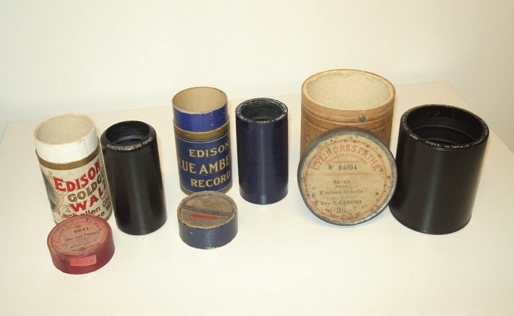
Figure 2: Replicated cylinders: wax (left), celluloid (centre) and wax “Pathé”.
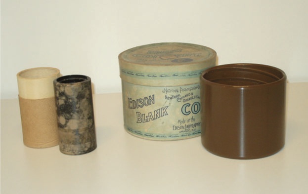
Figure 3: Self recorded cylinders: wax, affected by mould (left) and “Edison Concert” (right).
The various wax compositions used for wax cylinders are chemically fairly stable, if properly stored. Wax, however, is highly susceptible to fungus growths and, as many cylinders were inadequately stored in their earlier lives, fungal infection (mycosis) is commonly found. Fungi aggressively attack the surface of the cylinders and seem to aim for wax as their primary nutrition source. Additionally, the digestion process is associated with the secretion of acids and enzymes, further damaging the material of the cylinders. Complete removal is not possible. Prevention of further fungus growth is, therefore, of utmost importance. Chemical breakdown can also occur under the same conditions that promote fungus growth. Typically this takes the form of “efflorescence,” which can be mistaken for mould, but appears to involve the actual separation of constituent materials in the metallic soap composition.
Celluloid cylinders suffer from brittleness of their cellulose nitrate surface, but catastrophic deterioration as occurs in nitrate films has not been experienced. Mechanically, all wax cylinders and the plaster cores of celluloid cylinders are extremely fragile.
2.1.1.2 Coarse groove discs (gramophone discs)
Emile Berliner invented the gramophone in 1887. The groove is arranged as a spiral on the surface of a disc. Generally, the modulation of the grooves is lateral, as opposed to vertical for cylinders. Only a few disc formats (Pathé, Edison) have vertically cut grooves. The big advantage of the disc shape, apart from greater ease of storage, is that galvanoplastic negatives can be easily made and used for replication by pressing. As the number of pressings is limited, the first metal negative (“father”) serves only as a master for a metal positive (“mother”), which is used to produce an unlimited numbers of metal stampers (“sons”), which are used for the pressing tools for the replicated discs. This method, established at the beginning of the 20th century, is still being used for micro groove discs (“vinyls”), and for the production of replicated CDs, DVDs and BDs.
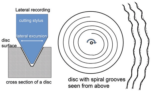
Figure 4: Coarse and micro groove discs recording principle.
2.1.1.2.1 Replicated coarse groove discs. The majority of coarse groove discs — the so-called shellac records — consist of a mixture of mineral powders bonded together by binders, originally containing shellac resin. These materials are chemically generally very stable if kept under fairly dry conditions. They are, however, fragile: when dropped, they break. Apart from shellacs, other record types existed in much smaller quantities and used different materials. These were often of lesser stability, for example, Edison Diamond discs, which are extremely susceptible to moisture.5
2.1.1.2.2 Instantaneous discs were recording media that were widespread in radio stations, before the advent of magnetic tape. The discs were used to record and replay signals without the need for galvanoplastic processing and pressing. Their surfaces are soft enough to permit the cutting of the groove, but hard enough to permit a number of replays. Most of these discs are unique recordings. If not recognisable by their distinct appearance, almost all instantaneous discs can be identified by their handwritten or typed labels.
There are homogeneous discs made from one single material component such as aluminium, zinc, PVC, or gelatine, as well as laminated discs, which are composed of a substrate and a surface coating made from different materials that is engraved with the recording.
2.1.1.2.2.1 Lacquer discs. The most widespread type of instantaneous discs is laminated: the lacquer or “acetate” discs. A lacquer coating consisting mainly of cellulose nitrate and usually plasticized with castor oil or camphor carries the information. The substrate that supports the information layer of the discs is generally of metal (e.g. aluminium or zinc); some are of glass, cardboard, or paper.
Lacquer discs can be easily identified as the base material can usually be seen between the outer lacquer layers, either within the centre hole or at the disc edge (IASA-TC 04, 5.2.2.5).
Cellulose nitrate decomposes continuously over time by reacting with water vapour or oxygen. This process produces acids that act as a catalyst for these hydrolytic reactions. Elevated temperature and humidity levels will further accelerate these reactions. Gradual degradation, along with loss of plasticisers, causes progressive embrittlement and shrinking of the lacquer coating. As the lacquer is bonded to a substrate that cannot shrink, internal stresses ultimately result in a cracking and flaking off of the lacquer coating, leading to the loss of the sound carrying layer. The mechanical instability of cardboard/paper bases often results in uneven or cracked surfaces while the fragility of glass bases often results in broken discs.
Figure 5: Metal based lacquer disc in the process of deterioration 1990–2001.
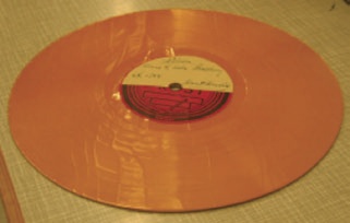
Figure 6: Cardboard based lacquer disc in the process of deterioration. (Stig-Lennard Molneryd)
Internal stresses are difficult to detect. Lacquer discs should not, therefore, be exposed to mechanical or thermal stresses. As their further life expectancy is unpredictable, the recordings on such discs should be immediately transferred to digital files before they are lost.
2.1.1.2.2.2 Other instantaneous discs. In addition to lacquer discs, all other instantaneous discs, irrespective of their particular composition, should also be considered to be at great risk.
5. For details of early coarse groove discs see St-Laurent 1996.
2.1.1.3 Microgroove discs (“LPs”, “vinyls”)
From the late 1940s onward a new material was used for replicated pressed discs: a co-polymer of polyvinyl chloride (PVC) and polyvinyl acetate (PVA) was introduced for two different new formats. The RCA record company launched a seven-inch (= 17 cm) disc that runs at 45 rpm for three minutes per side — in terms of duration, a continuation of the old shellac disc format. Columbia started the 10-inch (= 25 cm) LP, later enlarged to 12 inch (= 30 cm), both of which run at 331/3 rpm. Playing times are 15 and 25 minutes per side, respectively. This new material with its almost amorphous structure allowed much finer mechanical signal representation, which made narrower grooves, lower speeds and, therefore, longer playing times possible. The amorphous structure of the plastic also produced considerably less surface noise than shellac discs. PVC/PVA co-polymer, colloquially termed “vinyl”, is chemically very stable. Except for a few very early discs, an average vinyl disc is chemically in good shape. The material is comparatively soft, however, and therefore vulnerable to damage by scratching or abrasion.
In the early days of microgroove disc, small numbers were produced by injection moulding using styrene. These discs can be identified by their light weight and their relatively matte surface in relation to the shiny surfaces of “vinyls”. In reproduction, they have a higher surface hiss level than vinyl records. No systematic stability problems have been observed with this type of LP.
2.1.2 Deterioration by replay
2.1.2.1 General susceptibility. With all mechanical formats, mechanical replay will to some extent cause the shape of the groove to deteriorate. Specifically, cylinders and coarse groove discs played with historic equipment have often been damaged by the high inertia and excessive tracking forces of the old replay mechanisms. In addition, inappropriate stylus shapes and materials, and poor operation of the equipment, add to the groove damage. Microgroove discs also suffer from playback using low quality and/or misaligned equipment. As a result, most of the preserved mechanical records have not retained their original groove shape and sound quality. However, carefully chosen and adjusted equipment coupled with skilled operation permits the replay of all mechanical carriers without further deterioration.6
Cylinders, early shellacs, and all instantaneous discs must be handed over to experienced specialists. Shellac records from around 1930 onward and microgroove discs can be transferred by skilled staff with special training.
2.1.2.2 Alignment and maintenance of equipment. Pivoted tone arms of disc players need careful alignment of the following parameters:
- Effective tone arm length to minimise the (unavoidable) tangential tracking angle (TTA) error;
- correct setting of tracking force (“stylus pressure”);
- adequate skating compensation (“anti-skate”);
- correct adjustment of the height of the arm (parallel to disc during playback), which assures the correct vertical tracking angle (VTA), (see IASATC 04, 5.2.4, 5.3.4).
For tangential tone arms, alignment is restricted to the position of the stylus, and the tracking force.
Maintenance comprises:
- Frequent, careful cleaning of the stylus.
- Occasional cleaning of the platter and the driving belt.
- Tangential tone arms: occasional cleaning of the guide rails.
- Platter bearings: occasional lubrication with acid free low viscosity oil.
Only distilled water with mild detergent should be used for the cleaning of rubber and plastic components.
Modern cylinder replay machines must be aligned and maintained in close conformity to their manufacturer’s instructions and advice.
The keeping of log books for each piece of equipment and the careful documentation of all alignment and maintenance work is imperative.
6. Even wax cylinders will not suffer deterioration from a small number of replays by experts using good quality, modern equipment and well chosen pick-up styli. Optical replay of mechanical carriers has been explored by engineers for decades. One of the major arguments in favour —the avoidance of groove deterioration by mechanical replay—is, however, only of theoretical value. For optical replay and its potential see IASA-TC 04, 5.2.4.14.
2.1.3 Strategy for access to mechanical carrier collections
Because of their susceptibility to deterioration by replay, strategies have to be in place to restrict the replay of mechanical carriers to the absolute minimum. In pre-digital times, record collections of broadcasters and national libraries typically held at least two copies of mass replicated discs; one for access and one “untouchable” for preservation. Unique recordings on cylinders or instantaneous discs were transferred to magnetic tape of which at least two copies were held — again, one for preservation and the other for access. Such strategies must be pursued until long-term preservation through digitisation can be arranged (IASA-TC 04). In collections that have not been completely digitised, the request for access is often taken as a trigger to prioritise digitisation of that material.
2.2 Magnetic carriers
Magnetic recording was invented in the 19th century. Recording devices using steel wire or steel tape were used on a small scale in parallel to cylinders and gramophones. The technology became used on a greater scale with the development of magnetic tape in its modern form in the 1930s.
2.2.1 Recording principle
A magnetic carrier is moved across an electro-magnetic recording head. The head produces a magnetic field that varies according to the signal it receives from the recording device. This magnetic information is “frozen” within the magnetic carrier as it passes the recording head. The recorded signals can be retrieved by running the carrier across a replay head (sometimes identical with the recording head) that picks up the magnetic field and converts it back into an electric signal. With analogue audio tape recorders the head is stationary. Analogue video signals, as well as digital audio and video signals, require a considerably higher bandwidth than the analogue audio signal. This is achieved by greatly increasing the recording speed. This increase in speed cannot be done by simply moving the tape faster as the amount of tape required is excessive. The problem is generally solved by a rotating head which writes across the width of the tape with high speed, while the linear speed of the tape is much slower.
It is important to understand that, in order to optimally retrieve the signal from a tape, an intimate tape-to-head contact is essential, which is one of the reasons for keeping tapes, machines, as well as storage and handling areas, clean (see 3.5.1 and fig. 25).
For the specifics of hard disk recording, see 2.2.2.
By using the Kerr effect, magnetic information can also be read optically. This principle is used with magneto-optical carriers (2.3.1.4). It is also employed in the retrieval process of high-density computer back-up tapes. Reading conventionally recorded audio tapes by using this principle has not developed beyond an experimental state.
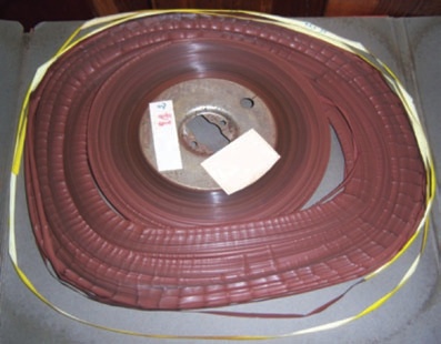
2.2.1.1 Magnetic tapes
In its present form magnetic tape recording was developed in the 1930s by AEG Telefunken and introduced for professional application in 1936. It became widely used within the German Radio. Because of World War II, however, its use was restricted to Germany. After the war it came to the United States from where it spread worldwide. In the late 1940s and early 1950s the use of this recording technology was concentrated mainly in the broadcast and recording industries. From the early 1950s onward, however, home audio recorders were developed which operated at slower speeds and employed half and quarter track formats to reduce the costs of magnetic tape. However, this was at the expense of recording quality. Also, during the 1950s, transistorised portable recording equipment became available that made sound recording possible everywhere in the world. This lead to a mushrooming of recorded sound collections, particularly in the fields of cultural, linguistic, anthropological, and ethno-musicological documentation. In the 1960s, cassette formats were developed. Of these, the compact cassette soon became the dominant format in the market, and is still in use.
In addition to magnetic tape, magnetic wire recorders were developed in the United States in the 1940s. They also gained some popularity in Europe in the 1950s and 60s.
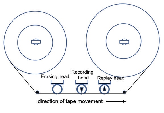
Figure 7: Principle of magnetic audio tape recording. In such “linear“ recording, the speed of writing is the same as the speed of the tape.
After several experiments, digital audio recording on magnetic tape was introduced in the 1980s. All of these early professional and semi-professional formats are now obsolete. In 1987 R-DAT (Rotary head Digital Audio Tape), a digital recording cassette format, was marketed and gained some popularity in semi-professional and professional circles. Since about 2005, however, it has also become obsolete. Now all audio specific magnetic tape formats are, in practice, dead. Audio recording, post production, and storage have become part of the IT (computer) world with its specific carriers and formats.
From 1956 onward, magnetic tape was also used for video recording. Several professional reel-to-reel formats were developed and in use until the late 1970s. They were followed by professional analogue and digital cassette formats. For home recording, early open reel formats were available from around 1970 and, around 1980, cassette home formats became widespread. Of these, the VHS format survived until recently. For small handheld camcorders (“handy cams”), an 8 mm cassette system became popular (Video8, VideoHi8), which was still in use in the early 2000s. Digital home formats were introduced in 1996. The Mini DV format dominated handheld camcorders from the early 2000s but has also become obsolete, replaced by optical, hard disc, and solid state (“flash card”) recording systems. The same development for the last remaining professional video tape formats is under way.
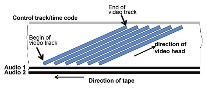
Figure 8: Principle of magnetic video recording. The high bandwidths of video signals require high recording speeds, which are achieved by a fast rotating head that writes narrow video tracks across a tape moving at a much slower linear speed. This principle of “helical scan” recording is also used for digital video formats and R-DAT.
Thus, video has developed in a similar way to that taken by audio. Proprietary video-specific formats are being replaced by file formats. Recording, postproduction and storage have, like audio, become part of the IT world.
Some video cassette formats have also been used for audio only recording purposes (IASATC 04, 5.5.7).
Beyond specific audio and video formats, magnetic media are the most prominent storage media in the IT world. Magnetic tape plays an important role as a computer backup medium and hard disc drives (HDD) have seen tremendous growth both in professional and home applications. Both carrier types have become the backbone of professional digital audio and video archiving. While this publication concentrates on (traditional) audio and video tapes, the basic principles described are valid for magnetic computer media.
2.2.1.1.1 Components of magnetic tapes and their stability
Magnetic tape is composed of two main layers: the base film and the magnetic layer. Additionally, many tapes are back matted for improved winding properties, and to reduce electrostatic charges.
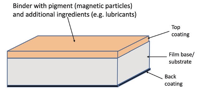
Figure 9: Layers of magnetic tape.
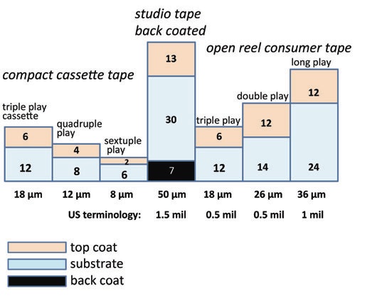
Figure 10: Cross sections of different audio magnetic tapes. Back coating may also be found on LP and DP tapes. (Friedrich Engel)
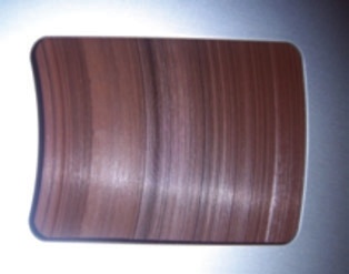
2.2.1.1.1.1 Base film materials. As magnetic tapes were developed, the following materials were used: paper, cellulose acetate (CA), polyvinyl chloride (PVC), polyester (polyethylene terephthalate, PET or PE), as well as polyethylene naphthalate (PEN).
Cellulose acetate was used from the mid-1930s until it faded out during the early 1970s. Such tapes can be identified by holding the tape pack against a light source: with some exceptions, it is translucent.
There are two processes of CA deterioration. One is hydrolysis, widely known and well researched in film preservation as “vinegar syndrome” (3.1.1.1). The other deterioration process is plasticiser loss: affected tapes become brittle.
CA audio tapes, in general, are much less affected by these deterioration processes than CA films. Specifically the vinegar syndrome seems to some extent to be a critical mass problem, which is less effective with audio tape. While hydrolysis is clearly related to high levels of relative humidity, which calls for low humidity storage, earlier literature (e.g. FIAF, 1.3, 11.2.4, 11.2.11.3) had recommended medium RH levels to prevent plasticiser loss. This is not confirmed by more recent literature.
CA audio tapes often also suffer from various geometrical deformations. As an intimate tapeto head contact is the basic requirement for optimal signal extraction, such deformations mean that the required contact cannot be achieved. Higher tape tension to improve tapeto- head contact is generally not applicable, as the tapes break because of their brittleness.7
It should be noted that severe cases of both kinds of deterioration—hydrolysis and embrittlement— mainly occur with German tapes from the early 1940s, and, more widespread, with tapes from East Germany and from the Soviet Union, produced well into the 1960s.
Figures 11 and 12: Typical brittle cellulose acetate tape before and after reconditioning (rewound on spool). The slipped tape pack can be rescued with the help of a “Wickelretter” (see 3.4.2.1 and figure 24).
Several other CA tapes are also affected. It should be noted, however, that some CA tapes from other production sources are still in good, flexible, and playable condition.
A comforting side effect of CA tapes is that they break without stretching (as opposed to PET, see below). This usually allows broken tapes to be spliced without the loss of recorded signals.
PVC tapes were mainly produced in Germany between 1944 and 1972 and as yet have not suffered from any systematic chemical deterioration. As plasticiser loss has not yet been experienced, tapes have maintained their flexibility. Due to their electrostatic behaviour, however, their winding properties are sub-optimal.
As practically all PVC tapes were produced in Germany, identification of professional tapes is easy because of the imprint on the back. Consumer tapes can be identified by the imprint on their leader tapes if the original ones have survived. Significant for all PVC tapes is their soft plasticity, which is a most welcome advantage when they are compared with CA tapes of similar vintage.
Apart from the early experiments in magnetic recording in Germany in the 1930s and occasional use after WW II, only a few paper based tapes were manufactured in the late 1940s in the U.S.
PET has gradually replaced CA and PVC tapes from the late 1950s onward. Since then, it has been used for all kind of magnetic tapes. It is mechanically fairly robust, and no systematic chemical deterioration of PET based films has been observed so far.8 However, unlike CA tape, PET elongates (stretches or “shoelaces”) before breaking, which leads to stretched tapes and unrecoverable signals. This calls for high precision replay machines and correctly adjusted tape winding, particularly when thin tapes are to be replayed.
Film base thicknesses vary between 30 µm for standard play audio tape down to 6 µm for thin audio and video cassette tapes. The thinnest CA and PVC bases produced are double play open reel tape (15 µm thickness), while thinner bases are possible with PET and PEN. PEN is used for thin digital video and computer back-up tapes.
In order to achieve stable bonding with pigment layers as well as back coating, base films are covered with thin layers (fractions of µm) of primers which are applied by the base film manufacturer or during the application of the magnetic layer.
2.2.1.1.1.2 Magnetic pigments. The very first magnetic pigment used in the 1930s was carbonyl iron. This was soon replaced, however, by a ferrous oxide (γFe2O3), which has been used for all open reel magnetic audio tape, compact cassettes of type IEC I, and the first video format (2 inch Quadruplex). γFe2O3 is brown rust and chemically stable. Because of the size of its elementary magnets, however, its capability to record the increased data density required by reducing recording speeds and tape widths was limited. In order to allow the development of smaller tapes still capable to handle the bandwidth of video signals, chromium dioxide (CrO2) was employed from the early 1970s. This permitted higher data densities, slower recording speeds and narrower tapes. Chromium dioxide and its substitutes (cobalt-doped Fe3O4) are dark grey in colour and have mainly been used for analogue video recording and for compact cassettes type IEC II. No critical observations have been made of chemical instability so far. From the mid-1970s, double layer cassette tape was produced: an iron oxide layer was covered by a thin layer of CrO2. Standardised as type IEC III, these cassette tapes gave improved signal-to-noise (S/N) ratios.
The latest magnetic pigment is made from pure iron particles (MP). It is used for digital video formats, R-DAT, and compact cassettes type IEC IV. Because of its chemical nature it is potentially prone to oxidation. After problems with early tapes in this respect, methods were developed that have prevented any widespread oxidation so far. However, in the midto long-term, MP tapes as well as ME tapes (tapes with a magnetic layer produced by evaporation under high vacuum) must be considered potentially endangered. MP tapes have a colour similar to chromium tapes with, however, a “metallic” reflectivity of their surfaces.
2.2.1.1.1.2.1 Stability of magnetic information. A constituent factor of magnetic information stability is the coercivity9 of a magnetic material. In the course of their development, magnetic pigments with ever-higher coercivity have been employed. The coercivity of carbonyl iron measures around 150 Oersted; average γFe2O3 tapes are between 300 and 400 Oe; CrO2tapes are typically 600-700 Oe; and MP and ME tape up to 1500 Oe. For data recording tape the coercivity can be above 2500 Oe.10
Apart from external fields, temperatures beyond the Curie point (3.2.1.5) and magnetostrictive action can destabilise magnetic orientation.
Magnetostriction is the disorientation of magnetic alignment by mechanical impacts. Except for very early Fe3O4 tapes, however, this effect is insignificant. Magnetostriction is positively employed for the erasure of unwanted print through signals on magnetic tape (IASA-TC 04, 5.4.13).
Contrary to widespread fears, magnetic information does not vanish with time. Properly produced, stored, and handled magnetic tapes will not lose their magnetic properties within historically relevant periods.
2.2.1.1.1.3 Pigment binders. Magnetic pigments are powders that need to be bonded together and onto the tape. In early tape production cellulose acetate was used, followed by copolymers of polyurethanes. Old CA binders are responsible for dry pigment shedding and are, therefore, regarded as a risk, as are CA tapes in general. In general, the bulk of the late 1950s and 1960s tapes have not shown severe binder deterioration problems.
Tapes from the 1970s and 1980s, however, frequently suffer from unstable pigment layers. This manifests itself as the shedding of the pigment layer in a sticky deposit—generally known as sticky tape or sticky shed syndrome (2.2.1.1.2).
2.2.1.1.1.4 Lubricants. Magnetic coatings also contain lubricants, generally fatty acids and esters, to minimise friction between the tape and the heads. The coating acts like a sponge that delivers lubricant through pores. The quantity of lubricant is greater for video than for audio because of the higher writing and reading speeds. The pores and, therefore, an adequate lubricant delivery, are determined by the calendering process in manufacture. Some lubricants have a tendency to exudate and crystallise on the tape surface, particularly stearic acid at temperatures below 8°C. This causes clogging of replay heads. Surplus lubricant can be removed mechanically, helped by elevated temperatures. Re-lubrication, as mentioned on several websites and publications, must be seen very critically, as it is impossible to restrict added lubricants to the small amounts actually needed. Superfluous lubricants are difficult to remove from tape guides, heads, and capstan and may interact with other tapes played on those machines at a later date (Schüller 2014).
2.2.1.1.1.5 Back matting originated in Germany to improve safe tape handling with flangeless hubs in radio studios. Back matting ensured a tight and safe tape pack without the risk of slipping apart. From the 1970s onward, back matting became more widely applied for audio and video tapes, generally by adding carbon black to improve conductivity to remove electrostatic charges which, together with the slight surface roughness, improves winding properties.
7. Several authors, however, report that the replay of brittle tape can be improved if stored for a period under high humidity conditions: vapour temporarily replaces the lost plasticiser. Recently, processes have been developed to make brittle tapes playable, refreshing the elasticity permanently by substitution of a plasticiser (Oesterreichische Akademie der Wissenschaften 2012, Wallaszkovits et al. 2014).
8. A theoretical breakdown scenario discussed in the 1990s did in practical use not materialise.
9. Coercivity is the property of a given magnetic pigment to resist changes in magnetic orientation or re-orientation (= "erasure"). It is defined by the level of the magnetic field needed for (re-)orientation, expressed in Oersted (Oe). The higher the coercivity, the higher the resistance of magnetic information to re-orientation (or erasure) by external magnetic fields.
10. In analogue audio recording these different coercivity values have been the major reason for the need to adjust the bias for each tape type.
2.2.1.1.2 The so-called Sticky Tape or Sticky Shed Syndrome (SSS)
From the mid-1970s onward, sticky tapes and pigment shedding have been frequently observed. These tapes often squeal during replay due to friction because of sticky pigment and binder particles deposited on tape guides and audio and video heads. This clogs the heads and leads to a significant loss of high frequencies (audio), or a complete breakdown of the signal (video).
Hydrolysis of pigment binders has been the most frequent explanation for these problems. Because this kind of hydrolysis is reversible to some degree, such tapes generally can be reconditioned for replay by exposing them to low humidity and elevated temperatures (or a combination thereof: for details see IASA-TC04, 5.4.3.4).
Recent research11, however, reveals that there are several additional possible reasons for the stickiness of tapes: primer exudation, surplus of dispersion agents, lubricant exudation, and, finally, uneven dispersion of hardener. Except for the latter, which is incurable, treatment similar to that of binder hydrolysis can be used: elevated temperature12 coupled with mechanical cleaning. This will help make tapes reproducible during a time window that is long enough to permit the transfer of their contents.
11. Schüller 2014.
12. Temperatures employed in such processes have varied between 60°C (for audio only) and 40°C. As elevated temperatures may mechanically distort tapes, which is specifically critical for video tapes, and may also have a negative influence on the further life of the tape, present thinking suggests to use the lowest possible temperature which is still effective.
2.2.1.1.3 Production process and individual integrity of a given tape as stability factors
Production process and individual integrity of a given tape as stability factors. While the chemical composition is an indispensable basis, the production process is regarded to be of even higher importance for tape stability: coating speed, proper dispersion of components, temperature and pressure of calenders are only some of the factors determining the stability of pigment layers. This may lead to a different performance between batches of the same type of tape, sometimes even with the same batch.
Additionally, the physical integrity of the tape surface plays an important role. Poorly serviced replay equipment can scratch the tape surface and create ports of entries for destabilising agents, such as humidity.
Chemical analyses are, therefore, of limited value in evaluating the quality and predicting the further life expectancy of tapes. Moreover: as the composition and production of tapes vary greatly, research results and recommendations valid for one type, or even only for a particular batch of tape cannot necessarily be extrapolated to others, let alone all tapes. In this respect generalising statements and/or recommendations by publications based on a limited number of normally not even identified sample tapes, should be regarded critically (Schüller 2014).

Figure 13: Pigment shedding: Chemical deterioration or poor manufacture?
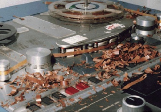
Figure 14: Rare case of total loss of pigment. This is most likely a production problem.
2.2.1.1.4 Deterioration by replay
Unlike mechanical carriers, fairly modern and well preserved magnetic tape can be replayed several hundred times without any measurable loss of quality. However, a pre-condition is well maintained replay equipment of the latest generation, which allows gentle handling of the carriers. Older or poorly serviced machines may severely damage, if not destroy, a tape during replay.
2.2.1.1.4.1 Alignment and maintenance of equipment (replay only). Magnetic tape players need careful alignment of the following parameters:
- vertical position, azimuth, and wrapping angle of replay head (Whenever head adjustment has to be changed to compensate for errors of the recording head of a given recording, it is imperative that the heads be re-aligned to their correct settings immediately after the playback is completed.);
- vertical position of tape guides to ensure horizontal tape travel and to avoid asymmetrical position of tape packs on reels and open hubs;
- calibration of tape tension in the play and winding modes, particularly if thin (amateur) and brittle cellulose acetate tape is to be played;
- alignment of the replay amplifier according to speed and equalisation standard (Alignment is head-dependent, therefore changing head blocks for different track formats will require re-alignment of the replay amplifier, or amplifiers switchable to different pre-settings.).
Maintenance comprises:
- the cleaning of tape heads and tape path (Frequency of cleaning is dependent on the abrasiveness of tapes in use. All surfaces of the tape path must be kept in perfect condition in order to avoid any scratching of the tape surface (2.2.1.1.3) as well as to avoid irregular speed fluctuations and to guarantee smooth tape-head contact.);
- frequent (daily) demagnetising of tape heads and tape guides (3.7.2.1.1);
- complete check of alignment and recalibration every 50-100 hours playing (not running) time.
The keeping of logbooks for each piece of equipment and the careful documentation of all alignment and maintenance work is imperative (IASA-TC 04, 5.4.)
2.2.1.1.5 Strategy for the access to magnetic tape collections
Although, in contrast to mechanical carriers, magnetic tapes can be replayed several hundred times without measurable deterioration of the recording, provided modern and well maintained equipment is employed, there is a statistical risk of damage to tapes through unforeseen malfunction of replay equipment. In particular, thin (LP, DP and TP) open reel tape and all cassette formats are prone to such rare, but unpredictable threats. In the analogue era this has led to a strategy of copying vulnerable original tapes to sturdy studio tapes and to making listening copies for recordings in frequent demand. Whether digital repositories are already in place or not, this strategy is still valid in the digital era, as most original digital audio and video recordings are extremely vulnerable. CDs and DVDs have proved ideal media for access copies (but not for master or preservation copies). As with collections of mechanical carriers, a request for access is often a trigger to prioritise the digitisation of that material.
2.2.2 Hard disk drives (HDD)
Hard disks (today generally called hard disk drives or HDDs) have been developed as computer storage devices since the mid-1950s. The prototype of today’s hard disks was the “Winchester” drive developed in 1973. Since the mid- 1980s, technical development has led to ever increasing capacities at continuously declining prices, which has made HDDs the main storage media, both for personal computers and, in particular, for mass storage systems. This development has also led to the decline in the use of recordable optical disks as storage devices after having been popular for audiovisual contents storage in the later 1990s and the early 2000s.
2.2.2.1 Recording principle and components. Hard disk drives consist of one or more rotating disk platters, normally made from aluminium, glass, or ceramics, covered with a thin (10-20 nm) ferromagnetic layer and mounted on a spindle. When in use, present day disks rotate at speeds between 4,200 and 15,000 rpm. A magnetic head, usually one, sometimes several, for each platter, writes and reads the information to and from the magnetic layer.
The head is mounted on a motor driven actuator arm, which permits the fast access of any part of the disk. In order to permit the closest proximity to the disk, yet avoid damage of the magnetic layer, the magnetic head is engineered with an aerofoil shape that allows it to ride on an air (or other gas) cushion that keeps it away from the surface. The head “flies” at a distance of fractions of a nanometre (just a few gas molecules in depth) from the disk surface in order to read short wave length signals. This spacing distance is important to avoid fatal head crashes caused by the head making contact with the surface of the disk. HDDs must not, therefore, be exposed to mechanical shocks during operation.
Until recently, longitudinal recording, comparable to recording on conventional magnetic tape, was standard. Since 2005, perpendicular recording has been introduced which permits higher data densities of three times or more than conventional longitudinal recording.
Originally rotating in air, platters in modern disks are also embedded in a helium atmosphere. The disk is sealed, which protects it to some extent from any intrusion of dust particles. Temperature is also a critical factor: manufacturers quote 40-55°C as maximum temperatures for safe disk operation.
2.2.2.2 Disk sizes. Today, the main sizes of hard disk drives are 3.5 and 2.5 inch. Smaller disks, developed for sub-note books are fading away, if not already obsolete, and are being replaced by solid-state memories.
2.2.2.3 Life expectancy. Life expectancy (LE) of hard disk drives is often referred to by “Mean Time Between (To) Failure” (MTBF or MTTF) which for current products is quoted to be between 1 and 1.5 million hours. However, these figures are extrapolated from laboratory tests and say nothing about the LE of a given medium. More realistic metrics of failure are AFRs, annualized failure rates, which quote the probability of a disk failure, expressed as the percentage of failing disks amongst a large population in relation to their age. Typical values quoted are below 10% for the first five years. Still, neither of these values allows a meaningful prediction of the actual life expectancy of a given individual disk. SMART pre-failure alerts are, however, highly correlating indicators of possible later failures if adequately monitored.
The practical commercial lifetime of a hard disk in a server environment, specifically its economic serviceability, is a key factor. Typically, hard disks are kept in operation between three and seven years.
Debates on HDD shelf storage over longer periods (several decades) have not led to any conclusive results.
To summarize, an individual hard drive is an inherently unreliable data carrier. However, storing multiple copies of each file in a well-managed mass storage system consisting of multiple hard disk drives with self-checking and self-healing protocols is an efficient and safe method of long-term storage (IASA-TC 04, 6.3.14-21).
2.2.3 Magneto-optical carriers (MODs)
While the information is stored magnetically, the recording and the reading process is optical. Because of their similar architecture with optical discs, MODs are discussed under 2.3.1.4.
2.3 Optical carriers
Optical carriers are the oldest audiovisual carriers. They have been in use for analogue image representation for more than 170 years. For the storage of audio and video signals, however, they are amongst the youngest group of carriers. Although optical tape formats have been developed, they have not reached market acceptance. Therefore, optical audio and video carriers are restricted to disc13 formats.
13. Spelling of disc vs. disk; this publication joins the orthography of IASA-TC 04, second edition: all analogue and optical discs are spelled discs; magnetic disks are spelled disk.
2.3.1 Recording principle
This is different to photographic carriers, which work by absorbing varying amounts of light. Optical discs rely on the creation of tracks of microscopic size that change the reflection of a laser beam, thus permitting the retrieval of the recorded signal.
The ancestor of optical discs was the Laser Vision Disc, which was developed for analogue video signals in the late 1970s. The technology and format parameters, but not the size, were taken over by the Compact Disc which was marketed as a replicated or pressed digital audio format in 1982 (CD-A, defined as Red book standard). It was soon discovered that, beyond audio, CDs would also be an ideal medium for the dissemination of general data, such as text, graphics and moving pictures, which in 1985 gave birth to the replicated data CD (CD-ROM14, Yellow book standard). In 1987 the interactive CD (CD-I, Green book) followed. By 1991 recordable CDs (CD-Rs, Orange book standard) and rewritable CDs (CD-RW, also Orange book standard) were developed. Finally, in 1993 a video CD standard (CD-V or VCD, White book standard) was defined, which has gained great popularity in East Asia.
In order to increase the capacity of optical discs, mainly to make them suitable for the storage of video films, the DVD (Digital Versatile or Video Disc) was introduced from 1995 onwards using the same recording principles as CDs. By reducing the laser wavelengths and thus reducing the track dimensions, the storage capacity was increased by a factor of 7 for each DVD layer. By 2005/2006, storage capacity was increased again to make optical discs capable of storing HDTV signals. Of the two competing formats, the HD DVD and the Blu-ray Disc (BD), the Blu-ray ultimately succeeded, while HD DVD was suspended. Blu-ray makes use of short wave lasers (“blue-violet laser”) which permits a further step in the miniaturization of signal representation and thereby an increase in data density.
Finally, magneto-optical discs (MOD) should be mentioned in this context. Originally used in the computer world for storing data, they have lost their earlier importance with the dramatic increase of storage capacity of hard disc drives (HDD) at ever lower prices. In the consumer world they have gained some popularity, however, in form of the (rewritable) MiniDisc (MD).
2.3.1.1 Replicated CDs, DVDs and BDs (-ROMs). These discs consist of a transparent body of polycarbonate, 1.2 mm in thickness, replicated by injection moulding using a negative metal “stamper”. The upper surface of this body carries a spiral track of “pits” (holes) and “lands” (flat areas) of varying lengths. The “pitted” surface is covered by a reflective layer of aluminium, which is covered by a protective lacquer. This surface also carries the content /label information. A laser “reads” the information from underneath: It is focused so that it hits the pits and lands that form the track. The depth of the pits is ¼ of the laser wavelength, which gives a change in the reflection of the laser beam at the transition between pits and lands. Such changes represent digital 1’s while no change represents 0’s.
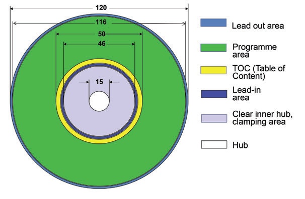
Figure 15: The partition of a CD-ROM; figures in mm.
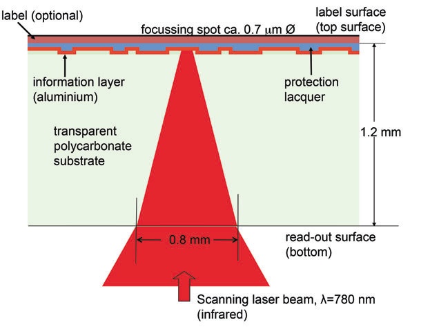
Figure 16: Layer structure and reading principle of a CD-ROM.
DVDs have narrower tracks and shorter pit/land lengths than CDs: they use a shorter wavelength laser. The basic disc is only 0.6 mm thick. With single sided DVDs, a blank second carbonate layer is bonded to the information carrying half. With double sided discs, a second information-carrying half is attached. Additionally, it is possible to add a second, semi-transparent layer (dual layer) to each data layer. This makes two layers readable from each side, almost quadrupling the storage capacity.
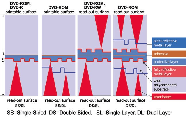
Figure 17: Layer structures of DVDs
Replicated Blu-ray discs (BDs) consist of two laminated polycarbonate bodies of different thicknesses. The lower, thinner one carries the pit-land track on its upper side covered by the reflective layer. The track is narrower than that of a DVD or CD. The upper, thicker polycarbonate body carries the label on its upper surface. Unlike DVDs, there are no double sided discs, but dual layer BDs are available.
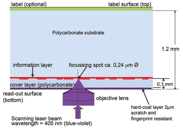
Figure 18: Layer structure of the Blu-ray disc.
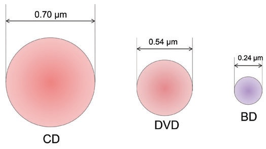
Figure 19: Focusing spots of CD, DVD, and BD.
2.3.1.2 Recordable optical discs (“Dye Discs”, CD-Rs, DVD-Rs, BD-Rs). The information layer consists of a groove in the upper surface of the polycarbonate body filled with an organic dye. Recording is made by a laser of much higher energy than the reading laser, which heats (“burns”) the dye. By this process, a sequence of burned and non-burned spots are created. The transitions between burnt and un-burnt areas are recognized by the reading laser in the same way as the pits and lands of replicated ROM-discs. Reflecting layers are of gold, silver, or silver alloy.

Figure 20: Injection moulded pits and lands (left) vs their burnt equivalents (centre and right) in CD-Rs (Jean-Marc Fontaine).
2.3.1.3 Rewritable optical discs (CD-RWs, DVD-RWs, BD-RWs). The information layer consists of a phase-changing metal alloy. Recording is made by a writing laser that heats up the metal alloy film at the exposed spot, inducing a phase change from crystalline to amorphous and vice versa, controlled by the burning temperature of the writing laser. Dielectric layers on both sides of the metal alloy film cause rapid cooling; the heated spots keep the changed phase after cooling. The amorphous film spots reflect the light of a reading laser with lower intensity than the crystalline areas allowing the transition between states to be recognised. Data can be erased and rewritten for a limited number of times (up to 1000 times).
2.3.1.4 Magneto-optical discs (MODs). The information layer is magnetic while the recording and reading process is optical. The recording is achieved by heating the magnetic information layer with a laser beam beyond its Curie point (3.2.1.5), which allows magnetic (re-)orientation by applying a very low magnetic field. The replay process makes use of the Kerr effect (see also 2.2.1), by which the magnetic orientation of the information layer causes different angle reflections of the reading laser. Actually magnetic carriers, for handling and storage purposes magneto-optical discs are grouped with optical discs proper, as their architecture is very similar.
Magneto-optical discs (more frequently spelled disks) were in professional use as a data back-up and transport medium in the 1990s. They came in different sizes (90 and 130 mm) and different storage capacities, and were housed in cartridges for protection against mechanical damage and foreign matter. With the development of hard disk drives (HDDs, 2.2.2) and their increasing storage capacities at ever-lower prices, magneto-optical discs have lost their importance.
2.3.1.5 MiniDisc (MD). The MiniDisc was introduced in 1992 as a replacement for the analogue compact cassette. It was popular for consumer use for over a decade, until its use faded in the later 2000s. It comes in two versions: as a magneto-optical disc (2.3.1.4) for recording purposes and as a replicated disc for pre-recorded content, which technically is like a CD-ROM. MiniDiscs are 2.5 inch (64 mm) in diameter and are housed in a cartridge, which makes them relatively resistant against mechanical damage and foreign matter. For their replay see IASA-TC 04, 5.6.10.
14. For the terminology of the classification of optical discs, this publication follows the recent development: originally replicated discs used for general data were called CD-ROMs (ROM=Read Only Memory). With the advent of recordable/rewritable CDs, this terminology became inconsistent. Recent publications on optical discs divide them into -ROM (replicated), -R (recordable), and -RW or -RAM (rewritable). All three types may contain audio, video, or general data.
2.3.2 The components of optical discs and their stability
The polycarbonate used for optical disc bodies is a transparent polymer with a low thermal expansion factor. It is resistant against deformation by heat at temperatures of up to 130°C. Early discs, especially LV discs, sometime had problems with crazing which made the polymer opaque and unreadable. From experience gained since the introduction of CDs in 1982, it can be expected that modern polycarbonate discs will be stable for several decades.
Apart from gold, all of the metals used to provide the reflective layers are prone to oxidation. Therefore, the protective lacquer layer of CDs plays an important role. It must be resistant against penetration of humidity, a function that often did not work properly with early CDs. Oxidised reflective layers, particularly aluminium, render optical discs unreadable.
The stability of the adhesive that keeps the two polycarbonate parts of a DVD or a BD together is unknown.
The stability of the dyes used in recordable CDs, DVDs and BDs is a factor of great uncertainty. There are three different dyes in use: cyanine, phthalo-cyanine, and azo. All dyes are susceptible to light, specifically uv radiation: an exposure of recordable discs to daylight will render them unreadable within a few weeks. Another uncertainty factor is the decrease in the amount of dye used for discs designed to run at higher recording speeds.
The life expectancy of dyes is often quoted to be between 5 and 100 years, an item of information that is of little practical use. The stability of the semi-transparent layers of DVDRs and BDs is unknown. Finally, the stability of rewritable discs is also unknown, and their potential life expectancy as compared to dye discs is unclear.
2.3.3 Deterioration by replay
There is no (measurable) deterioration by replay with optical discs.
2.3.4 Alignment and maintenance of equipment
Optical disc readers are non-adjustable mass-produced products, which is part of the problem explained below (2.3.5). Maintenance is restricted to occasional cleaning of the lens with the help of a cleaning disc, and of the loading tray.
2.3.5 Recording quality as a constitutive factor of life expectancy of recordable optical discs
Recordable optical discs (CD-Rs, DVD-Rs, BD-Rs) have become very popular media for audio, video, and data recording. As with many other digital carriers, their reliability depends on a sophisticated error correction system that permits the full reconstruction of the information even if small parts of the medium have become unreadable because of damage or deterioration by ageing. The correction capability is limited and, therefore, the quality of the recording becomes an important factor of life expectancy. A perfect, almost error free recording leaves more correction capacity to compensate for handling and ageing effects and, therefore, enhances the life expectancy. If, however, optical discs start their life with a high error rate, then there is little capacity left to compensate for further errors. The life of such discs will be shorter. Consequently, IASA has defined recommendations for maximal acceptable errors for optical discs in order to maximize their life expectancy, whatever it may be (IASA-TC 04, 8.1.9).
A major problem in burning recordable optical discs is the interaction between blanks (unrecorded discs) and writers. There are no standards defined, and the processes of automated adjustment do not always work sufficiently well. Tests have shown that randomly chosen blank/writer combinations produce 50% acceptable, and 50% unfavourable results. Consequently, to reliably burn recordable optical discs would need extensive testing of writer/blank combinations, control of each single disc produced, and further checking at regular intervals. As testing is labour intensive and test equipment is expensive, more reliable and, ultimately, more cost effective storage systems than recordable optical discs are used for professional data storage.15
15. J.-M. Fontaine, 2000.
2.3.6 Formats and sizes
Analogue Laser Vision Discs were manufactured in 300 and 200 mm sizes, mainly double sided, i.e., two discs bonded together back-to back. For the digital disc family, diameters are 120 mm for all types of discs apart from some CDs and BDs which are available in 80 mm diameter.
2.4 Solid state carriers
Solid-state memories are electronic circuit storage devices without any moving parts. These have been developed since the 1950s using various technologies. Of particular interest in the context of this publication are the so-called flash cards, developed since the 1990s. As removable data carriers they come in various formats (SD and several others) and as so-called USB-sticks. With an increase in storage capacity, accompanied by a dramatic drop in price, they have become popular as removable data carriers and, more recently, as replacement for HDDs in lightweight notebooks.
2.4.1 Recording principle and stability. Flash memories belong to the group of non-volatile solid-state memories, which retain their information without power supply. The memory cells consist of transistors, which can hold their information for many years. While reading capacity is generally described to be indefinite, programming/erase cycles are quoted to be between several thousand up to one million. Because of their relative sturdiness against mechanical shock and extended temperature ranges, they were originally employed in military applications.
As to their life expectancy, no realistic guesses are available. This is of minor interest as long as prices are significantly higher than HDDs. This makes them (still) unattractive for longterm storage. Although, in general, flash memories have proved their robustness for short term storage, specifically for location recording even under adverse conditions, it is imperative not to rely on a single carrier but to copy the contents at the earliest opportunity to another storage medium before arranging transfer to a secure digital storage system.